SHAPES for Blender
SHAPES is an advanced shape key editor for Blender. Built with production-tested workflows in mind and inspired by the needs of industry professionals, SHAPES offers a complete and unified toolset for creating and editing shape keys in character articulation and facial rigging.
SHAPES for Blender is the sibling of the same tool for Autodesk Maya®, a production-proven tool used in games and feature films by studios and educational institutions worldwide.
1. Introduction
1.1 Overview
SHAPES is a complete toolset for working with shape keys, enabling efficient and structured workflows. It extends Blender’s native shape key system with features tailored for character articulation, focusing on minimizing technical overhead while supporting advanced production requirements.
The heart of SHAPES is a user-friendly, artist-driven shape key workflow. Developed with input from industry professionals and designed specifically for the needs of artists, SHAPES builds on Blender’s standard shape key functionality to offer a cohesive suite of tools and automation features. It streamlines the creation, editing, and management of shape keys, enabling intuitive, production-ready setups for any project scale, from quick prototypes to complex character rigs.
Shape key setups generated with SHAPES are fully compatible across Blender versions and do not depend on the add-on at runtime. This ensures portability and longevity of the work, even in studio environments or collaborative pipelines. The only exception is the optional RBF Nodes extension, which - when integrated - enables advanced shape blending setups and must be present during animation playback or rendering if used.
1.2 Key Features
- One-click shape creation
- Symmetry mapping for fast mirroring
- Shape organisation and filtering
- Shape import and export
- Driver setup and interactive driver editing
- Shape key Combos with multi-level propagation
- Influence Map for dividing a complex shape into multiple sub-shapes
- Extended weight map functionality
- Shape animation and shot fix utilities
- Raw shape key data export
- Setup rebuilding
2. Installation and Setup
SHAPES is implemented as an Extension for Blender 4.2 and later, which replaces the traditional add-on system for some functionality.
2.1 Installing the Extension (Blender 4.2 and later)
- Download SHAPES.zip.
- Drag-and-drop the archive into the Blender window.
- Choose a User Repository from the drop-down menu.
- Make sure the Enable Add-on option is checked.
3. Interface Overview
SHAPES is available as a dedicated sidebar panel in the 3D View.
3.1 Restrictions
SHAPES is designed to provide a complete toolset for shape key workflows and, as such, is intended to be used independently of Blender’s default Shape Key panel found in the Mesh Data Properties tab. The standard Blender panel does not support the extended functionality offered by SHAPES, such as grouping or nested hierarchies within the Target List. Additionally, the shape key order shown in Blender’s default UI is not synchronized with SHAPES, which may result in inconsistencies or data loss if both systems are used in parallel.
For this reason, it is strongly recommended to avoid manipulating shape keys outside the SHAPES interface while actively working on a setup. Reordering, renaming, or otherwise modifying shape keys through Blender’s native tools can lead to unexpected results and break the internal structure maintained by SHAPES.
Summary
- SHAPES should not be used in parallel with Blender’s default Shape Keys panel.
- The two lists are not synchronized (ordering and grouping).
- Reordering or editing shape keys outside SHAPES can lead to unexpected behavior.
Avoid modifying shape keys outside of SHAPES while it is active. Doing so can result in corrupted setups or misaligned data.
3.1.1 Working with Linked Meshes
When a mesh is linked from an external file, Blender restricts most forms of direct editing. This means that a wide range of features of SHAPES, such as adding new shape keys or editing weight maps, are not available for linked meshes. This is not a limitation of SHAPES but a fundamental restriction of Blender's linking system. What is possible, however, is managing and animating shape keys that already exist on the linked mesh. If you need to add new shape keys to a linked mesh, this has to be done in the source file first. Linked meshes and rigs are expected to already have a functional shape key setup ready for animation.
Nevertheless, SHAPES supports loading of linked meshes, mainly for creating post-deformation shape keys for corrective animation. Because SHAPES handles these corrective shapes through Geometry Nodes, the linked mesh data itself does not need to be modified.
When loading a linked mesh, any existing SHAPES data is internally copied to the scene to allow further usage and editing. This data is contained in the scene and does not transfer back to the original linked source file. When the linked object is removed from the scene, any SHAPES data associated with it will no longer be connected to an object, though it will remain stored in the scene file.
3.2 Workflow
Unlike typical Blender tools, which operate strictly based on the current selection and context, SHAPES uses an explicitly loaded object as the target for all operations. Once an object is loaded into SHAPES, all tools and processes act on that object, regardless of selection changes elsewhere in the scene.
This design choice enables a more robust and predictable workflow, especially in complex production environments. It decouples the editing process from Blender’s context-dependent logic and allows for a more streamlined and user-centric approach to building and maintaining shape key systems. As a result, artists can work more efficiently without worrying about accidental context switches or selection conflicts interfering with shape key creation and management.
Summary
- SHAPES relies on a loaded object, not the active selection.
- All tools operate on the loaded object, allowing for consistent workflow without context switching.
- Shape key editing and creation are centralized in the SHAPES panel.
3.3 Object Compatibility
Currently, SHAPES is designed exclusively for use with mesh objects. Other object types are not supported at this time.
3.4 Object Loading
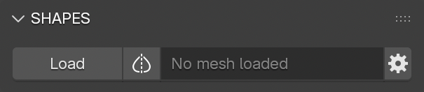
The top section of the SHAPES panel is dedicated to loading the mesh object to be edited. This is the only visible part of the panel when no object has yet been loaded.
This section includes:
- A button to load the object to be used for the shape key setup. Currently, only mesh objects are supported.
- A button indicating the Symmetry Map status. Pressing this button opens the menu for managing the Symmetry Map. See Symmetry Map for more information.
- A text field displaying the name of the currently loaded object.
- A Preferences button, which opens the SHAPES Tool Preferences .
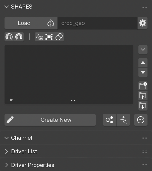
Once a mesh object is loaded into SHAPES, the full panel expands to reveal the remaining interface.
By default, when loading a mesh for the first time, SHAPES automatically evaluates the mesh and creates a Symmetry Map. This process typically goes unnoticed for standard meshes, but with dense meshes it may cause a slight delay. See Symmetry Map for more information.
If the loaded mesh belongs to a collection that is currently disabled, most of the SHAPES interface will be inactive, and a message will indicate that the mesh is not part of the active View Layer.
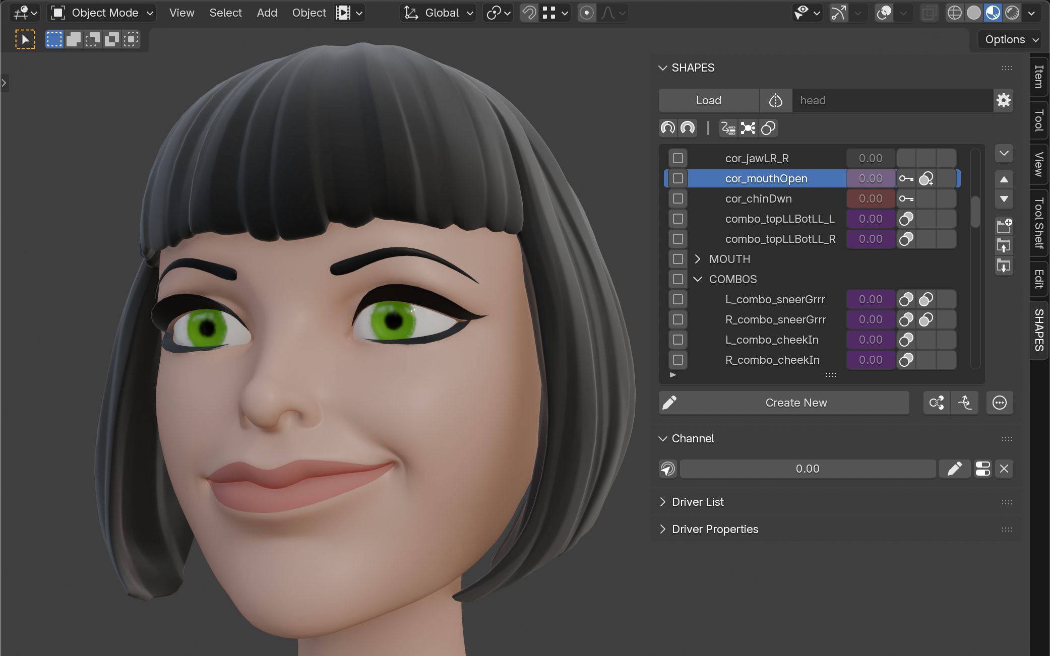
3.5 Target List
The Target List displays all elements included in the current shape key setup, along with additional information and controls. It is the core component of SHAPES, functioning as both a visual overview and a central hub for controlling relationships, Combos, and behaviors of shape keys.
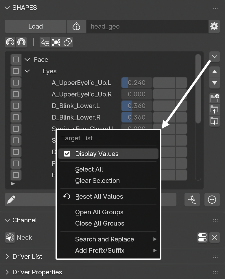
By default, the Target List does not display values for shape keys. This display can be enabled through the Target List Menu by activating Display Values. Note that these values are shown for visual reference only and cannot be edited directly.
Each Target List item includes a set of buttons, alongside the item name and an optional value:
- Selection Checkbox: Used to select the item. Since the list widget does not support multi-selection, checkboxes make it possible to mark multiple items at once.
-
Button Columns: Three columns of buttons provide quick visual feedback and access to related functionality:
-
Input Column: Indicates whether the item is controlled or driven. This represents any incoming data affecting the item, such as:
- keyframe animation
- standard Blender driver
- Shape Driver
- RBF Nodes driver
- Combo
- Output Column: Shows if the item is driving another item via a Combo.
- Vertex Groups: Indicates whether the effect of the shape key is restricted by a vertex group.
-
Input Column: Indicates whether the item is controlled or driven. This represents any incoming data affecting the item, such as:
To improve organisation, the Target List supports grouping. This is especially useful in setups with a large number of shape keys, allowing artists to sort shape keys as needed.
See Organisation for grouping and sorting details.
Important: The right-click context menu of the Target List has no effect. Because Blender does not provide a way to suppress the default right-click menu for custom lists, it may appear as if the available commands are functional, although they are not.
If, for example, specific target items need to be keyed, use the keying buttons in the Animation panel or the default Blender Shape Key panel instead.
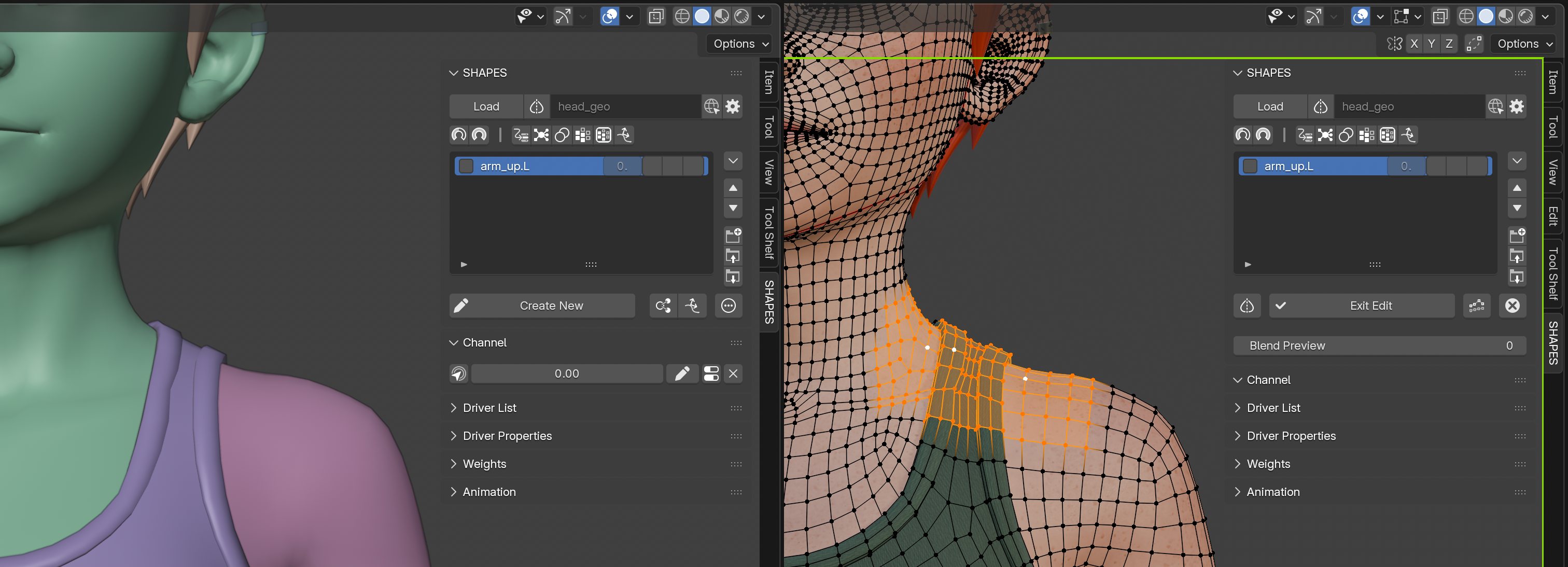
3.6 Edit Button
Located directly below the Target List, the Edit button is used to create new shape keys. Once pressed, SHAPES enters Edit Mode, and the button changes into a new set of controls that allow you to either finalize the creation of a shape key or cancel the operation.
This process is detailed further in the Edit Mode section.
3.7 Channel
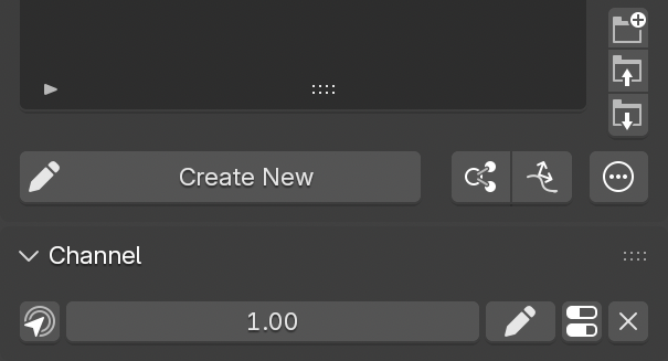
The Channel section displays all the controls related to the currently selected shape key. Similar to Blender’s default Shape Key Properties panel, it only shows information and settings for one active shape key at a time.
The Channel section includes:
Commands
A list of commands that can be applied to the selected shape key or a selection of shape keys. See
Channel Commands
.
Value Slider
Adjusts the value of the currently selected shape key or selection of shape keys.
Since this control can affect multiple shape keys simultaneously, special handling considerations apply:
-
When adjusting the value, the slider may temporarily display values that exceed the defined range of the affected shape keys. This is a known technical limitation. After releasing the mouse button, the slider updates to reflect the actual stored value.
-
If one or more of the affected shape keys are driven, the associated drivers are automatically muted during the value change. This allows for interactive value editing and immediate visual feedback. Drivers are reactivated once the change is complete.
-
If the value stops changing but the mouse button remains pressed, the driver may be reactivated before the interaction fully completes. This can result in an unexpected visual change to the affected shape. This is a technical limitation. The reactivation delay can be adjusted with Channel Release Time in the Add-on Preferences.
These behaviors are due to limitations in Blender’s driver and UI system and are handled as gracefully as possible by SHAPES.
Tweak Shape
Allows editing of the current shape key by entering
Edit Mode. This can be exited using this button or the general
Exit Edit Mode
button below the
Target List.
Settings
Opens a popup menu providing access to basic shape key settings, normally found in Blender’s
Shape Key Properties
panel.
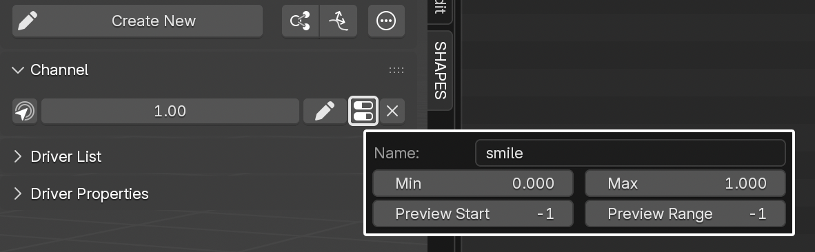
The available settings include:
- Name: Allows renaming of the selected shape key or group. Since Blender’s custom list UI doesn’t support inline renaming, it must be done here.
- Min/Max: Defines the minimum and maximum values of the shape key slider.
- Preview Start: The Blend Preview start frame.
- Preview Range: The default number of frames on either side of the Blend Preview start frame.
Delete
Deletes the currently selected items from the list.
When deleting the group item of an RBF setup, the associated solver is removed as well.
The controls in the Channel section are hidden while in Edit Mode to prevent execution of commands that could interfere with the current editing state.
4. Edit Mode
SHAPES uses a custom Edit Mode to create and modify shape keys.
Key differences from Blender’s native behavior include:
- Shape keys do not need to be pre-created. A new shape key is automatically generated upon exiting Edit Mode.
- Shape key editing does not require switching to Edit or Sculpt Mode manually. SHAPES handles this transition behind the scenes when you press the corresponding action button.
To indicate that
SHAPES
’
Edit Mode
is active, a colored frame appears around the 3D View.
The frame can be disabled in the
Tool Preferences
, and its color and width can be adjusted in the
Add-on Preferences
.
The SHAPES Edit Mode also differs from the standard Blender approach to editing shape keys, as it creates a mesh duplicate as an intermediate for editing, which is then applied as a shape key. This is necessary for SHAPES ’ custom shape extraction process, but it also allows the shape key to be properly edited in the deformed state of the mesh within Blender’s Edit Mode.
During the editing process the original mesh is hidden to avoid visual clutter.
The controls in the Channel section are hidden while in Edit Mode to prevent execution of commands that could interfere with the current editing state.
4.1 Blend Preview
Since shape keys are usually tied to animation, it’s important not only to focus on the shape itself but also to consider the related motion. A shape may look fine when fully triggered, but during blending, neighboring vertices can move at different speeds, or faces may stretch too much or too little.
These issues often only become visible after setting up drivers or establishing dependencies. At which point it may be necessary to return to Edit Mode, tweak the mesh, then exit again to check the results. Sometimes this process must be repeated multiple times before the deformation looks right.
Blend Preview addresses this by allowing to view the effect of the currently edited shape directly in relation to the underlying animation, without leaving Edit Mode or setting up a driver.
When activated, the current edit state is temporarily converted into a shape and blended with the deforming mesh. While active, Blend Preview allows to scrub the animation within a defined range, starting from the current frame. During playback, the shape is automatically blended in and out to preview its effect in combination with the mesh deformation.
After Blend Preview is deactivated, mesh editing resumes normally.
Blend Preview works best with a Range of Motion (ROM) animation, where the rig cycles through all extreme poses over time. This makes creating and adjusting shape keys much easier. For example: Bending an elbow starts at frame 50, reaches full bend at frame 70, and returns to default at frame 90. The corrective shape would be authored at frame 70. With Blend Preview, it’s possible to immediately check how it blends during the motion of the bend, before finalizing and setting up the driver.
Blend Preview is disabled for post-deformation shape keys and in Shot Fix mode.
4.1.1 Interpolation
While active, Blend Preview blends the edited shape with the deformed mesh at the current frame. Since it’s only a preview, there’s no real driver-driven relationship, so the results may differ slightly from the final deformation once a driver is applied.
For instance, if the ROM animation uses smooth interpolation but Blend Preview is set to linear, the preview will not appear fully in sync with the animation.
To better match the underlying animation, Blend Preview provides three interpolation modes, available in the Tool Preferences :
- Linear: Standard linear interpolation.
- Smooth: Similar to smooth animation easing at start and end.
- Mixed: Smooth interpolation near the start frame, then blending to linear.
4.1.2 Preview Start and Range
Each shape stores two Blend Preview properties:
- Preview Start: The frame at which the shape was created (automatically set).
- Preview Range: The number of frames around the start frame where the preview applies. By default, the range is 20 frames in each direction (for a total of 41 frames). The default range can be adjusted in the Tool Preferences .
These properties can be set individually in the Channel settings.
4.1.3 Blend Preview Tools
Blend Preview can be activated in two ways:
4.1.3.1 Blend Preview Tool
The
Blend Preview Tool
is a modal operator, triggered by the default keymap
Alt + C + Left Mouse Button.
Dragging left/right moves the time slider and adjusts the blending. Releasing the mouse resumes shape editing.
The mouse sensitivity (how fast time changes during drag) can be adjusted in the Tool Preferences.
4.1.3.2 Blend Preview Slider
If using a keymap to initiate the Blend Preview Tool is not an option, Blend Preview can be accessed through an optional slider in the interface while in Edit Mode.
- To use it, Blend Preview Slider needs to be activated in the Tool Preferences .
- When Edit Mode is active, the slider is displayed below the Exit Edit and Cancel Edit buttons.
- Dragging the slider activates Blend Preview and blends the shape relative to the animation.
- After dragging stops, Edit Mode resumes automatically after a short delay. Since Blender provides no event to detect when a user stops dragging a property, the deactivation is based on time. The time delay can be adjusted in the Add-on Preferences .
4.1.4 Blend Preview Action
When using Blend Preview, a dedicated Action can be used to evaluate the currently edited shape within a controlled range of motion. This Action can differ from the main Action assigned to the deforming Armature, which may serve broader purposes such as animation playback or general testing.
To extend the available motion range for shape creation, SHAPES provides the option to switch to an alternative Action while in Blend Preview. This is achieved through a suffix-based naming convention defined in the Tool Preferences.
The suffix is dot-separated from the base Action name. When entering Blend Preview, SHAPES evaluates the Armature associated with the loaded object and reads its currently assigned Action. The target Action is then derived by replacing the existing suffix with the one defined in the preferences, while preserving the base name.
For example, if the current action is rigAction and the suffix is set to blendPreview, SHAPES will switch to rigAction.blendPreview for the duration of the session. The original action is restored automatically when exiting Blend Preview.
This approach allows the rig to operate in a neutral or predefined state during shape editing, without modifying or interfering with the primary animation Action.
4.2 Conform Shape
When creating shape keys, it is often difficult to maintain the original correlation between neighboring vertices, especially when covering large changes in shape. This can introduce unwanted stretching or compression of the surface, which may become visible in surface details and texture maps.
Even though the Blend Preview tool helps visualize the shape key in relation to the underlying deformation, unwanted vertex movement can still be overlooked.
Conform Shape
attempts to preserve the relative placement of vertices in the edited shape in relation to their original positions. This means that vertex distances supporting particular surface features are maintained as much as possible, even if the edited shape differs significantly from the original shape.
The algorithm compares each edited vertex to its neighbors using the original edge lengths as weights. This allows the system to detect when a point moves differently from the surrounding surface flow.
Overall, Conform Shape behaves similarly to Blender’s Smooth Corrective modifier, but provides several advantages:
- Precise control per shape, as opposed to processing the entire mesh.
- Improved performance, since no additional modifier is required.
- Only edited vertices are affected.
- Reduced loss of volume in the affected areas.
- Respects changes in local scale rather than relying solely on local weights.
- Fully integrated workflow.
Considerations
-
Conform Shape should be used as a tool to improve and refine the currently edited shape. It is not intended as a fully automated solution to always produce a perfect result. Its purpose is to help identify and correct unwanted vertex movement, and it should be used in a controlled manner.
-
Consecutive operations may lead to volume loss in some cases, but may also be necessary in others.
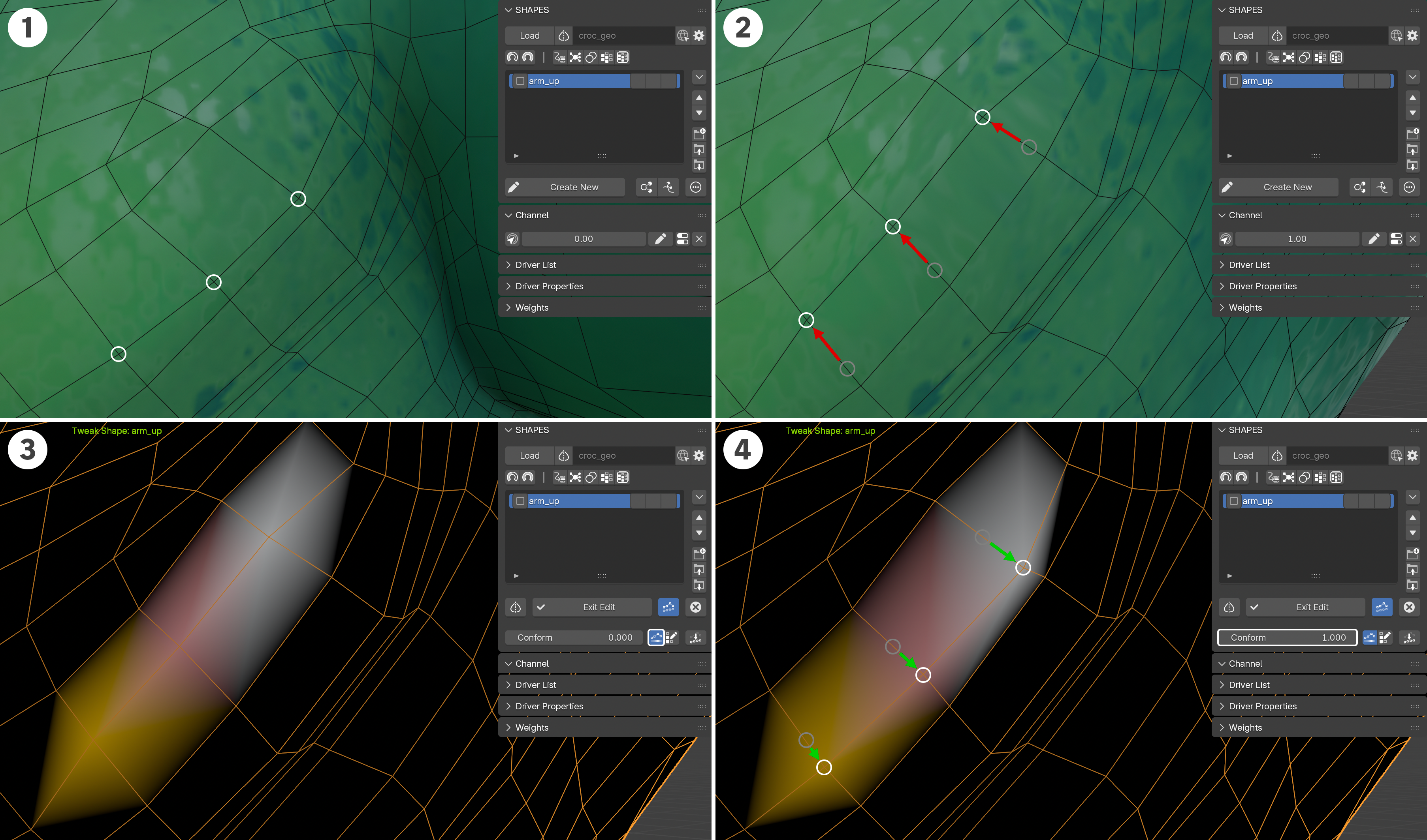
4.2.1 Conform Mode
Visualizing the current deviation and conforming the shape is only available while in Edit Mode.
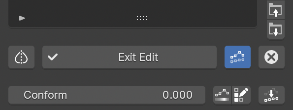
While in Edit Mode, press the Conform Shape button. This adds an additional row of controls below the Exit Edit button. These include:
Conform Value
This slider acts as a preview to show the result after applying the correction to the current shape. A value of 1.0 displays the full correction. The value is also used when applying the correction to the edited mesh.
Deviation
Enables a preview mode that displays the current vertex deviation as a color map on the mesh. The displayed colors resemble a standard heat map, where blue represents small changes and white represents maximum movement. The value range is normalized to the current maximum deviation.
This maximum value is maintained as long as
Conform Mode
is active. This ensures that subsequent corrections use the same reference value, allowing the heat map display to be evaluated consistently.
The displayed colors do not represent a linear mapping of the deviation values; instead, a smoothstep interpolation is used, reducing emphasis on smaller values while highlighting larger deviations.
Edit Weights
When entering
Conform Mode, a vertex group is created to provide additional control over which areas of the surface are affected by the conform operation.
Edit Weights
provides a quick way to modify these vertex group weights.
By default, only edited vertices receive full weight, making affected areas easy to identify.
When editing weights with Synchronized Objects, only one object can be edited at a time, as Blender allows only a single object to be in Weight Paint Mode. To edit a different Sync Object, select the object in the Outliner using its mode button to switch directly to it.
Conform
Applies the current deviation correction to the edited mesh. The correction takes both the vertex group weights and the
Conform Value
into account. For example, a vertex with a vertex group weight of 0.5 and a
Conform Value
of 0.5 will be corrected with an effective strength of 0.25.
If the mesh is in
Edit Mode
and has an active vertex selection, only the selected vertices are affected.
The edited mesh remains unchanged if no correction is applied and Conform Mode is exited.
Conform Shape does not work in conjunction with Blend Preview as long as no correction has been applied.
Conform Shape is disabled for post-deformation shape keys.
4.2.2 Conform Workflow
The following steps outline the general workflow for visualizing and applying shape correction with Conform Shape:
- Edit the shape as usual to represent the desired deformation.
- Press Conform Shape to enter Conform Mode.
- Adjust the Conform Value slider to preview how the edited vertices move toward their estimated positions based on the original mesh.
- Optionally enable Deviation to preview the deviation strength using a color representation.
- Optionally press Edit Weights to paint vertex group weights and refine which areas are affected.
- Review the result by adjusting the Conform Value.
- When finished, press Conform to apply the current correction to the mesh, or exit Conform Mode by pressing Conform Shape again without applying any changes.
4.3 Synchronized Shapes
A standard shape key workflow is designed to operate on a single object. In practice, however, a character or rig often consists of multiple meshes representing different parts of the model. If these elements are intended to deform together, creating and editing shape keys can become challenging, especially when precise relationships between the meshes are required.
Synchronized Shapes simplifies the creation of correlated shape keys across multiple meshes by allowing more than one object to be edited simultaneously. Editing multiple objects in a single process ensures maximum precision and consistency between the resulting shapes.
Note: Blender imposes certain limitations that affect the Synchronized Shapes feature. Most notably, Sculpt Mode only supports editing a single object, while Edit Mode allows multiple objects to be edited at the same time.
For this reason, SHAPES always enters Edit Mode when creating or editing synchronized shapes, even if Sculpt Mode is enabled in the preferences. Sculpt Mode can still be entered manually, but Edit Mode is used initially to clearly indicate that multiple objects are being edited.
4.3.1 Entering Edit Mode
Synchronized Objects (
Sync Objects) are defined as the objects selected at the time of entering
Edit Mode. In this case,
Edit Mode
includes both the currently loaded object in
SHAPES
and the additional selected objects.
To use this functionality, the
Synchronized Edit Mode
option must be enabled.
When Synchronized Edit Mode is enabled, the button displays one of the following icons:
- Select Object: No Sync Objects are selected. Entering Edit Mode affects only the currently loaded object.
- Active Selection: One or more Sync Objects are selected, all with a complete Symmetry Map.
- Inactive Symmetry Map: Sync Objects have no mapped vertices or missing map data.
- Partial Symmetry Map: Only parts of the mesh are mapped.
- Mismatched Symmetry Map: The number of vertices differs from the stored map data.
The Symmetry Map status of Sync Objects mirrors the mapping state shown when an object is loaded into SHAPES.
To create a Symmetry Map for a Sync Object, load it into SHAPES as the main object before using it as a Sync Object for editing.
Multiple Objects
When multiple objects are selected for Synchronized Edit Mode, the status icon reflects the lowest available Symmetry Map state among all Sync Objects.
This means that if all Sync Objects are fully mapped and one object has only a partial mapping, the status icon indicates partial mapping. If one object has no mapping, the status icon indicates that no mapping is present.
This behavior ensures that the displayed status represents the most limited mapping condition within the selection.
4.3.2 Exiting Edit Mode
After leaving Edit Mode, the resulting shape keys are added to all involved objects. The new shape key on the loaded object drives the corresponding shape keys on the Sync Objects. This ensures that whenever the main shape key is activated, all related shapes are activated accordingly.
The shape key item on the loaded object stores the names of the Sync Objects and their corresponding shape keys, maintaining the relationship for future edits.
Important: Because the relationship between the loaded object and the Sync Objects is name-based, neither the Sync Objects nor their shape keys should be renamed outside of SHAPES.
4.3.3 Working With Synchronized Shapes
The following steps outline the basic workflow for working with Synchronized Shapes:
- Ensure that all objects used for synchronized editing have a Symmetry Map if mirroring is required. To create a Symmetry Map, load each object individually into SHAPES. By default, a Symmetry Map is created automatically. For more information, see Symmetry Map.
- Load the main object into SHAPES to begin creating target shapes.
- Enable Synchronized Edit Mode.
- Select one or more objects to act as Sync Objects. The Synchronized Edit Mode button displays an icon indicating the Symmetry Map status of the selection.
- Press Create New to enter Edit Mode. The loaded object and all Sync Objects are selected, and Blender enters Edit Mode. If Sculpt Mode is enabled in the Tool Preferences, it must be entered manually, as it does not support multi-object editing.
- Edit the meshes. Blend Preview and Conform Shape are available for all objects being edited.
- Exit Edit Mode. New shape keys are created for the loaded object and all Sync Objects, and are linked via standard drivers.
- To tweak a target shape with Sync Objects, no additional selection is required. All synchronized objects and their shape keys are stored with the target item and are automatically used during editing.
Important: Because the relationship between the loaded object and the Sync Objects is name-based, neither the Sync Objects nor their shape keys should be renamed outside of SHAPES.
5. Preferences
SHAPES user preferences can be found in two places, each tailored to its purpose and usage frequency.
5.1 Add-on Preferences
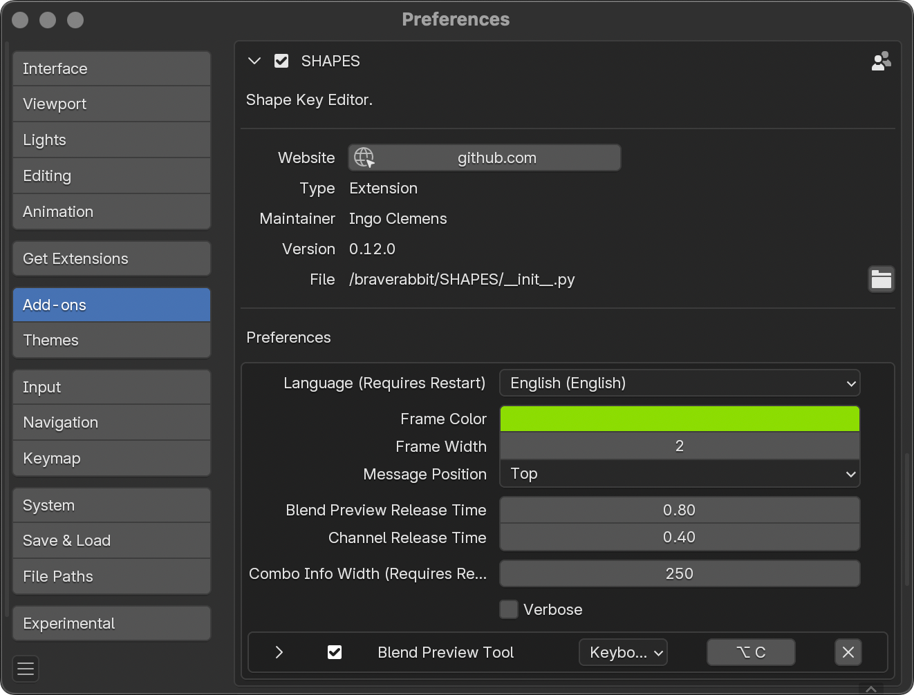
These preferences are more general and typically require adjustment only during the initial setup. These are located under Edit > Preferences > Add-ons > SHAPES.
- Language: Sets the interface language. A restart of Blender is required for changes to take effect.
- Frame Color: Defines the color of the frame displayed around the 3D View during SHAPES Edit Mode.
- Frame Width: Sets the thickness of the Edit Mode frame in the 3D View.
- Message Position: Determines the on-screen location of the message indicating that SHAPES Edit Mode is active.
- Blend Preview Release Time: Defines the delay (in seconds) after dragging the Blend Preview slider before Edit Mode is resumed. Since Blender provides no event to detect when a user stops dragging a property, this switch is handled based on time.
- Channel Release Time: The time after dragging the channel slider to change one or more target values until drivers are unmuted. If drivers are connected to the target items the switch is visible when the drivers regain control over the target values. Because Blender provides no event which can be run when the user stops dragging a property with the mouse, switching between modes is time based.
- Combo Info Width: Defines the width of the Combo info panel, allowing longer target item names to be displayed. A restart of Blender is required for changes to take effect.
- Verbose: Writes the Symmetry Mapping process results to the console output. This is intended solely for debugging purposes.
- Keymaps: Custom key mappings for additional tools can be defined here.
5.2 Tool Preferences
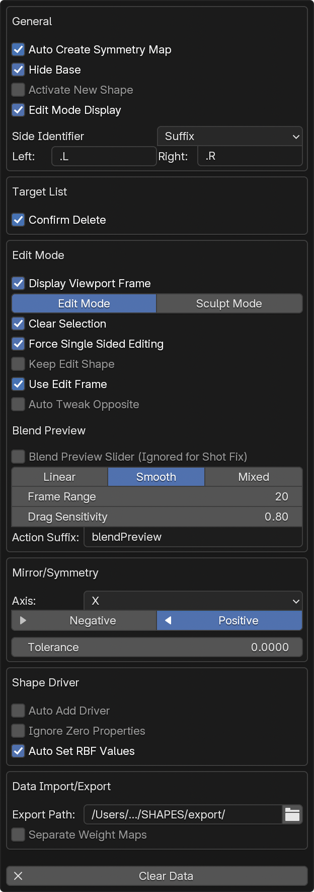
These options affect the active workflow and may be adjusted more frequently to suit the user’s needs.
5.2.1 General
- Auto Create Symmetry Map: Automatically generates a Symmetry Map upon loading a mesh when no existing mapping is present.
- Hide Base: Hides the base shape key from the Target List used as the reference.
- Activate New Shape: Automatically activates a new shape key after exiting Edit Mode. If enabled, this replicates the default behavior in Blender 5 and later. The option only affects new shape keys created in Edit Mode. Any other actions that create new shape keys will always set the value to zero.
- Edit Mode Display: Displays shape keys in Edit Mode instead of the undeformed mesh. This replicates the Shape Key Edit Mode button from Blender’s default Shape Keys panel.
- Side Identifier: The type of side identification used when splitting shapes. Suffix is the default.
- Left/Right: The labels used to identify sides. It is recommended to also use a separation character, such as a period or underscore, to improve readability. Leaving the fields empty resets the labels to their defaults (.L and .R).
5.2.2 Target List
- Confirm Delete: Shows a confirmation dialog when deleting items from the list.
5.2.3 Edit Mode
- Display Viewport Frame: Toggles the colored frame around the 3D View during Edit Mode.
- Shape Editing: Chooses the preferred editing method: either Edit Mode or Sculpt Mode.
- Default Brush: Selects the default brush for Sculpt Mode. Only visible when Sculpt Mode is chosen.
- Clear Selection: Clears any selected vertices for all objects when entering Edit Mode. Since the editable mesh is a duplicate of the loaded object, vertex selections exist on both objects. This can be useful but also disruptive, so enabling this option by default helps avoid confusion.
- Force Single Sided Editing: Automatically turns off mesh mirroring when editing shape keys to ensure that only one side is edited.
- Keep Edit Shape: Keeps the edited shape in the scene after exiting Edit Mode.
- Use Edit Frame: When tweaking a shape, moves the timeline to the animation frame where the target was created. This option only applies if the target item has an edit frame stored, and the value is not set to its default of -1.
- Auto Tweak Opposite: Automatically adjusts the opposite sibling shape to match changes made during editing.
- Blend Preview Slider: Displays the Blend Preview slider in the panel while in Edit Mode.
-
Blend Type: Defines how the shape fades out from the start frame to mimic animation interpolation.
- Linear: Standard linear interpolation.
- Smooth: Smooth interpolation with easing at the start and end of the range.
- Mixed: Smooth interpolation at the start and linear at the end of the range.
- Frame Range: Sets the default number of frames on either side of the Blend Preview start frame.
- Drag Sensitivity: Controls how quickly dragging with the Blend Preview tool changes time. Higher values result in faster time changes.
- Action Suffix: The suffix used to identify the action for Blend Preview. The suffix is dot-separated from the base action name, which must match between the current action and its substitute. For example, if the current action is rigAction, the Blend Preview action would be rigAction.blendPreview.
5.2.4 Mirror/Symmetry
- Axis: Defines the axis of symmetry. By default, this is set to the X-axis.
- Direction: Sets the direction for mirroring. By default, this is from positive to negative.
- Tolerance: Specifies the tolerance used to find symmetrical points. Lower values enforce stricter accuracy, while higher values may lead to false assignments. For Topological Symmetry, this is used to locate a base center edge. For Partial Symmetry, it is used to find matching point positions. If set to 0 (the default), an automatic internal value is calculated based on edge length. For Topological Symmetry, it is generally best to leave this value at 0, while for Partial Symmetry a small tolerance is recommended. When adding Partial Symmetry, selecting two vertices can be used to automatically determine the tolerance if the property remains set to 0.
The properties are not shown in advance, but only after the mesh has been loaded. They are also not global add-on preferences but are properties owned by the active mesh object.
5.2.5 Shape Driver
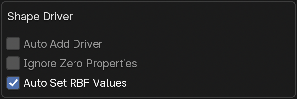
- Auto Add Driver: Automatically creates and assigns a shape driver when a new shape is created.
- Ignore Zero Properties: Lists only non-zero properties for a shape driver, omitting any properties with a value of zero.
- Auto Set RBF Values: Automatically sets the value of a newly added target item as a pose to 1, and sets all other pose target values to 0. This simplifies the process of adding poses by reducing the need to manually ensure that other items are correctly set. This option assumes that only one target item should be active for each pose.
5.2.6 Data Import and Export
- Export Path: The path used to export or import shape key setup data. Specific data is stored in subfolders within the defined path. This path is saved as a scene-based property and is unique to each scene.
- Separate Weight Maps: Saves each vertex group to a separate file during export instead of storing all vertex groups in a single file.
5.2.7 Other
Clear Data: Clears all non-shape key data to reset the list. This removes all groups and nesting information.
6. Channel Commands
The Channel Commands Menu contains all commonly used operators to edit the current list item or a selection of items.
6.1 Toggle Driver
This option is only displayed if the currently selected shape key is driven.
Enables or disables the driver assigned to the shape key. Since shape keys with active drivers cannot be manually edited, this toggle allows you to temporarily disable the driver for manual adjustment.
The driver is not automatically reactivated. The menu item icon reflects the current driver state.
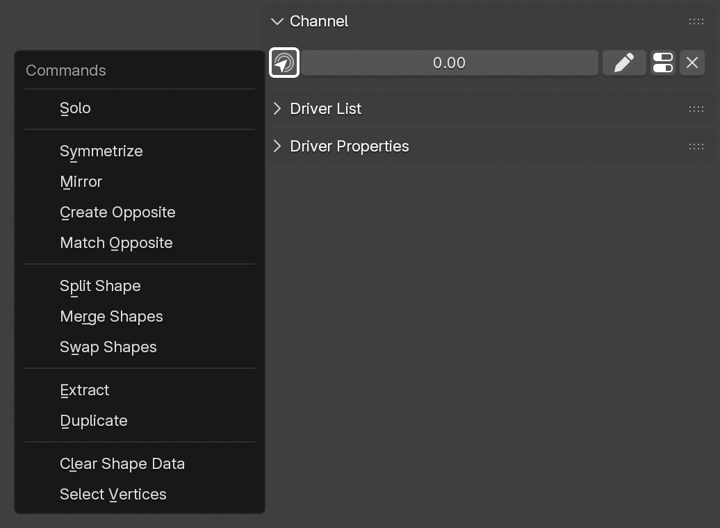
6.2 Solo
Displays only the active shape key at full value, temporarily hiding the influence of all other shape keys.
6.3 Symmetrize
Makes the shape key symmetrical so that both sides are identical.
It works on either the currently selected shape key or all shape keys that have their checkboxes enabled.
If the mesh is in Edit Mode and has an active vertex selection, only the selected vertices are symmetrized.
This operator is only available if a Symmetry Map has been set up for the loaded object.
6.4 Mirror
Mirrors or flips the entire shape in place, so that the features on one side appear on the other side.
It works on either the currently selected shape key or all shape keys that have their checkboxes enabled.
If the mesh is in Edit Mode and has an active vertex selection, only the selected vertices are mirrored.
This operator is only available if a Symmetry Map has been set up for the loaded object.
6.5 Create Opposite
Creates a new shape key as the mirrored sibling of the currently selected shape key. If the source shape key has a side identifier, the new shape key will be named with the opposite side identifier.
If the source shape key has a shape driver attached, a mirrored version of the driver will be used to drive the newly created opposite shape.
Depending on the orientation of the driver object or bone, the activation range of the driver can result in either matching or inverted values. SHAPES attempts to determine the correct mirrored value automatically, but this process can fail under certain conditions.
This is primarily due to the fact that the effective bone orientation depends on multiple factors, which can prevent a reliable calculation of the mirrored value. If automatic detection fails, the driver start and end values must be adjusted manually. Any changes are applied to the driver immediately.
It works on either the currently selected shape key or all shape keys that have their checkboxes enabled.
This operator is only available if a Symmetry Map has been set up for the loaded object.
6.6 Match Opposite
Matches the shape key that appears as the mirrored sibling of the currently selected shape key. It is important that the side identifiers are properly paired, or the operator will fail.
It works on either the currently selected shape key or all shape keys that have their checkboxes enabled.
This operator is only available if a Symmetry Map has been set up for the loaded object.
6.7 Split Shape
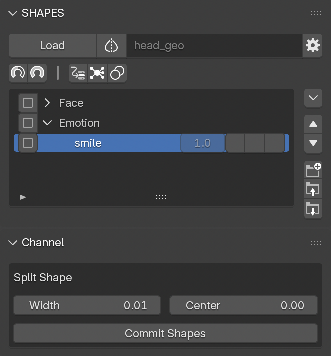
Split Shape creates two separate shapes from the currently selected shape key, divided along the line of symmetry. The process is performed in two stages:
1. Preview Phase
The initial step previews the split, based on the side defined in the
Tool Preferences.
If preferences are set to
Positive, the positive side is shown during preview; the negative side will be applied once the operation is committed.
Two properties can be adjusted during this phase:
-
Width:
Controls the blend width between the unmodified and the affected areas of the shape. Measured in world units. -
Center:
Defines the center position of the split. A value of zero results in a symmetrical split, but the center can be offset for asymmetrical or special shapes. Measured in world units.
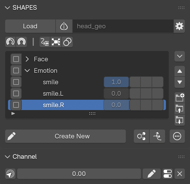
2. Commit Phase
When satisfied with the preview, finalize the split by pressing
Commit Shapes.
This generates two new shape keys representing each half of the split. These new shape keys are inserted directly below the original in the
Target List.
The values used for splitting the shape are stored with the shape key to ensure consistent results if the split needs to be repeated.
Naming is handled automatically:
If existing shape keys use side identifiers (e.g., prefixes or suffixes), the new shapes will follow the same naming style.
If no identifiable naming pattern is found, the side identifiers defined in the Tool Preferences will be used.
During the split process, some interface elements are hidden to focus attention on the current operation.
6.8 Merge Shapes
Merges all currently active shape keys with their current values into a new shape key. The new shape key is named based on all participating shapes.
6.9 Swap Shapes
Swaps the shape key data between two selected shape keys. This is very helpful if these shape keys already have drivers attached but their shapes need to be reversed.
6.10 Extract
Creates a new mesh object from the currently selected shape key.
It works on either the currently selected shape key or all shape keys that have their checkboxes enabled.
If the mesh is in Edit Mode and has an active vertex selection, only the selected vertices are extracted.
6.11 Duplicate
Duplicates the currently selected shape key.
It works on either the currently selected shape key or all shape keys that have their checkboxes enabled.
6.12 Clear Shape Data
Removes the shape key data from the selected shape key.
It works on either the currently selected shape key or all shape keys that have their checkboxes enabled.
If the mesh is in Edit Mode and has an active vertex selection, only the selected vertices are cleared.
6.13 Select Vertices
Selects all vertices influenced by the currently selected shape key.
7. Shape Driver
Shape keys are frequently employed for primary and secondary deformation. To automate their activation, drivers are used to trigger individual shape keys based on specific motions. While setting up drivers in Blender is generally straightforward, certain workflows that require precise value ranges can be more involved. SHAPES is designed to streamline this process with minimal manual intervention, supporting the overall workflow focus on design rather than technical overhead.
Shape Drivers are managed through the Driver Properties panel, which defines the driver object and property. SHAPES attempts to automatically detect the appropriate property and value range based on the current pose.
Any drivers utilized in the current setup are listed in the Driver List, enabling quick access for reuse.
Once a Shape Driver is assigned, the related properties become available for interactive adjustment, facilitating precise control over how the driver influences the shape.
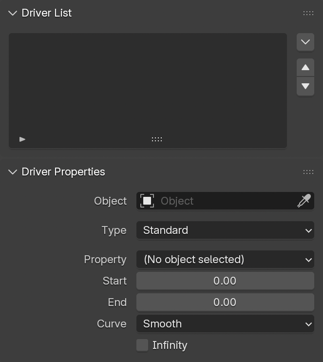
7.1 Driver List
The Driver List displays all objects and bones currently used as drivers for shapes in the active setup. This feature provides a consolidated overview and simplifies reusing driver objects or bones without reselecting them in the scene or through the property fields in the Driver Properties panel.
Any listed object is displayed alongside an icon indicating its type. Additionally, bones are differentiated based on their function, distinguishing those used for deformation from those intended solely for rigging purposes. This visual distinction serves as a helpful reference, particularly in complex rigs where numerous bones may exist with varying roles, ensuring quick recognition of their purpose within the driver setup.
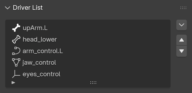
Selecting an item in the list automatically loads its data into the property fields of the Driver Properties panel.
7.1.1 Driver List Button Stack
A vertical stack of buttons adjacent to the Driver List provides organisational and management tools.
Available controls include:
Driver List Menu
Opens a popup menu with advanced operations:
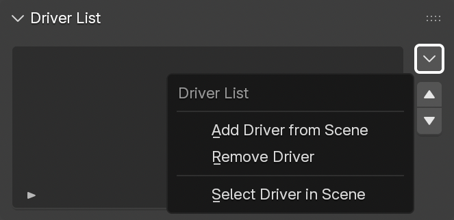
- Add Driver from Scene: Adds the currently active object or bone to the driver list.
- Remove Driver: Removes the selected item from the list.
- Select Driver in Scene: Selects the corresponding object or pose bone in the Blender scene.
Move Item Up/Down
Moves the selected item(s) one position up or down.
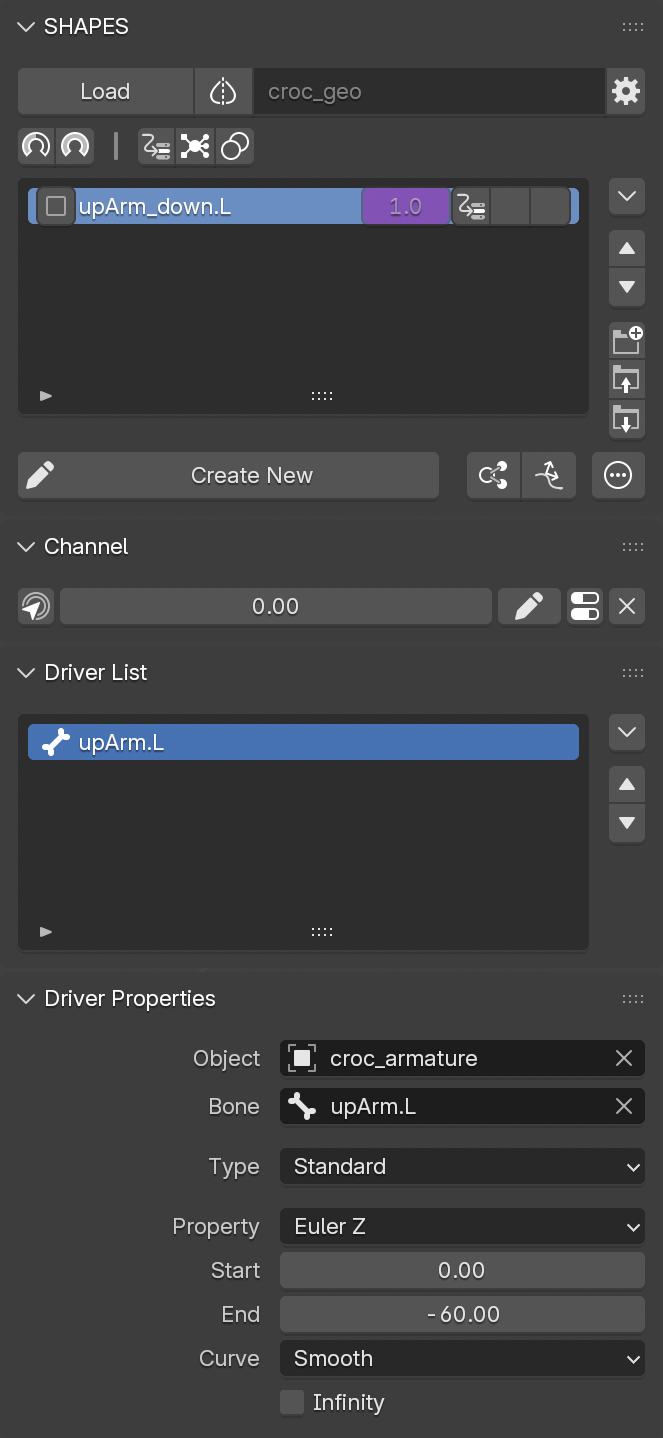
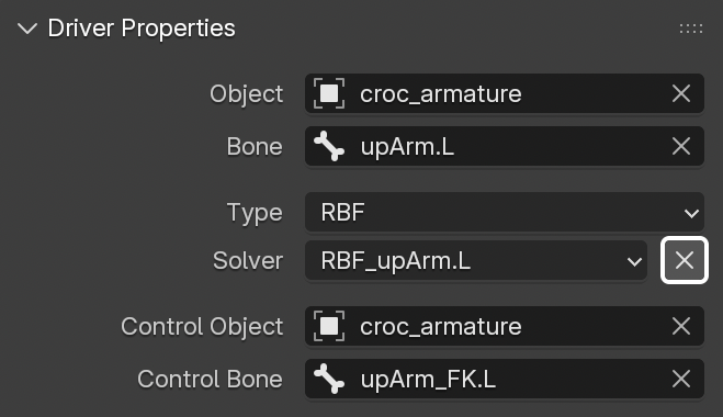
7.2 Driver Properties
The Driver Properties panel consolidates all settings needed to create or modify a driver. When a shape is selected in the Target List that is controlled by a driver set up with SHAPES, these properties reflect the active driver configuration.
Adjusting these parameters provides direct, interactive control over the influence of the driver on the shape, eliminating the need to manually rebuild drivers or adjust them in Blender’s native Drivers Editor.
Available properties:
Object
The object serving as the driver. If a previously used driver is selected in the
Driver List, this field populates automatically.
Bone
The armature pose bone acting as the driver. Automatically set if the driver was chosen via the
Driver List.
Type
The following driver types are available:
- Standard: A conventional Blender driver.
- RBF: Employs Radial Basis Function interpolation, if the RBF Nodes add-on is installed.
Property
The list of float-based properties which generally can be used for driving a shape. Since SHAPES’ basic workflow is based on working on a particular pose at a time, the property with the largest value is automatically selected.
For example, when creating a corrective shape for an elbow, the bone representing the lower arm is at a specific angle, while the other rotation axes are typically at zero. This makes it straightforward for SHAPES to determine which axis should be used to drive the shape.
In more complex cases where automatic detection is insufficient, the user is required to manually define which property should be used.
To further limit the list of properties, it is possible to use the preference setting Ignore Zero Properties from the Tool Preferences , which restricts the listed properties to those that are currently not at their default value of zero.
Start
The start value of the driver to be used to drive the shape. In most cases this is zero and is therefore assumed as such. This defines the value at which the driven shape will be off. Selecting a driving property automatically sets this value.
A rare exception for this value to be non-zero is when a Quaternion Rotation channel of an object is used as the driving property. For example, the Quaternion W Rotation of a bone is one in its rest pose, so the start value of the driving range would be one instead of zero. In such cases, this value requires manual adjustment. However, using individual Quaternion values is rarely a good choice for a driver.
End
The end value of the range used to drive the shape. This is automatically set based on the current values of the selected driver. It defines the point at which the driven shape will be fully turned on. Usually, when setting up a driver, this value does not need to be edited.
Curve
Controls the interpolation curve for the driver.
- Linear: Uniform influence between Start and End.
- Slow: Greater influence at the beginning, tapering toward the end.
- Fast: Lower influence initially, increasing toward the end.
- Smooth: Eased start and end transitions.
Infinity
When enabled, the driver continues to influence the shape beyond the defined
Start
and
End
values.
To allow shapes to exceed the default 0-1 range, adjust the Min and Max values under Channel settings.
7.3 Driver Setup
Attaching a driver to a shape is a two-step process:
-
Define the driver source
Set the Object and, if needed, the Bone in the Driver Properties panel. Based on the current pose, the driving properties are initialized automatically and usually require no further adjustment. -
Attach the driver
This step depends on the intended workflow:- Use an existing target item: Press the first (input) button of the corresponding target item in the Target List to attach the driver manually.
- Create a driver automatically for the next new shape: Enable the preference option Auto Add Driver in the Tool Preferences . When exiting Edit Mode, if the Driver Properties are set, a new shape driver will be created automatically.
7.4 RBF Nodes
SHAPES provides built-in support for the RBF Nodes add-on and extends its functionality by offering additional tools to copy and mirror RBF Nodes setups.
RBF Nodes is a node-based Radial Basis Function (RBF) solver for Blender. It allows multiple input values to drive multiple output targets, overcoming the limitations of Blender’s standard driver system, which typically supports only a single output per driver.
7.4.1 General Use of RBF Solvers in Rigging
RBF solvers are well-suited for rigging, deformation, and animation control. They are a widely adopted solution when working with corrective shapes, where linear driver setups often fail to capture the complexity of a pose.
Corrective Shapes: RBFs excel at blending shape keys smoothly across different poses, ensuring that intermediate states deform correctly.
Complex Driver Relationships: Unlike standard drivers, which map one input to one output, RBFs handle many-to-many relationships efficiently. This makes them suitable for facial rigs, limb deformation, or any system where multiple joints influence a result.
Rotational Problems: Standard drivers struggle when multiple rotation axes are involved. For example, using Euler angles often causes discontinuities and gimbal lock, while quaternions are not intuitive to drive directly. RBF solvers address this by interpolating across multi-axis input values, providing smooth transitions regardless of rotation order or axis dependency.
General Rig Integration: RBFs are commonly used to correct shoulder, hip, or wrist deformations, where bone rotations combine in nonlinear ways. They can also drive auxiliary systems such as muscle bulging or cloth-like deformation.
Even though RBF Nodes support various property types as drivers or driven outputs, the integration with SHAPES is focused on using transforms as drivers and shape keys as driven outputs.
7.4.2 Considerations
SHAPES takes advantage of the strengths of RBF Nodes and provides its own interface for creating and editing the necessary node trees.
-
The generated node groups containing solver setups remain accessible but are not intended to be edited manually.
-
SHAPES uses additional properties to manage generated node trees. Manual edits may interfere with SHAPES’ ability to access and update solver data.
All nodes generated by SHAPES should be left unchanged.
7.4.3 RBF Nodes Documentation
The following sections outline only functionality and procedures relevant to the SHAPES implementation of RBF Nodes. Since SHAPES uses RBF Nodes exclusively in the context of shape keys, not all features of the RBF Nodes add-on are covered.
For further explanation of features and properties unrelated to SHAPES, see the RBF Nodes documentation.
7.4.4 Workflow Overview
The following provides a short overview of the steps required to set up an RBF solver for a set of target items. A more detailed explanation of each step is provided in the subsequent sections.
- Define a driving object and, if applicable, a driving bone.
- Set the Driver Type to RBF.
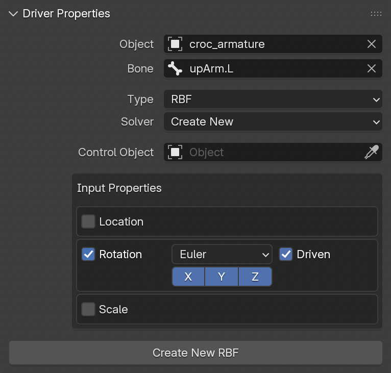
- If required, define a Control Object (and Bone).
- Verify the automatically set Input Properties. Adjust if necessary.
- Place the driver in its rest or default pose.
- Press Create New RBF to generate a new solver and node tree. A group item is added to the Target List.
- Move to the frame or pose where the first target should be activated and set its value (e.g., 1.0 for a standard shape key).
- Press the Create Shape Driver button of the target item to assign it to the current pose. The item is marked with an icon to indicate it as an RBF pose.
- Repeat steps 7-8 for additional poses.
- When all poses are assigned, enable Active in the RBF Solver panel.
- If required, fine-tune solver settings in the Advanced subpanel of the RBF Solver panel.
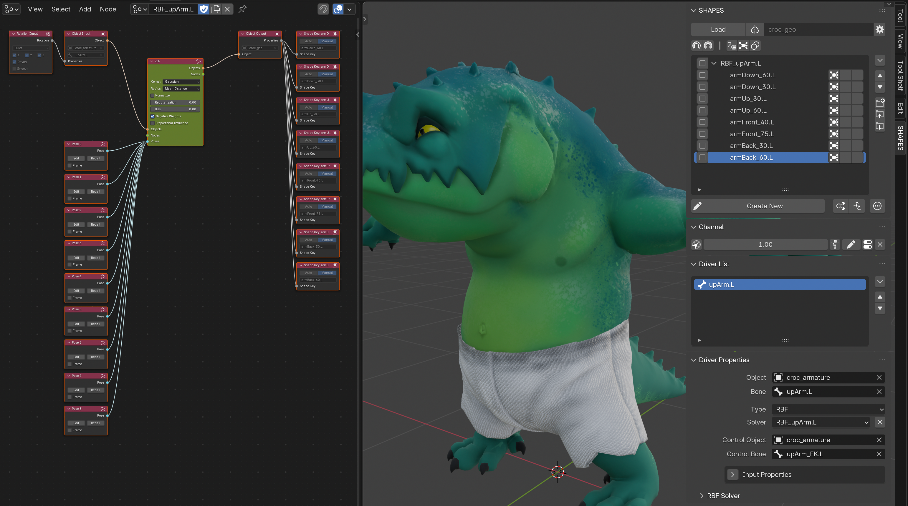
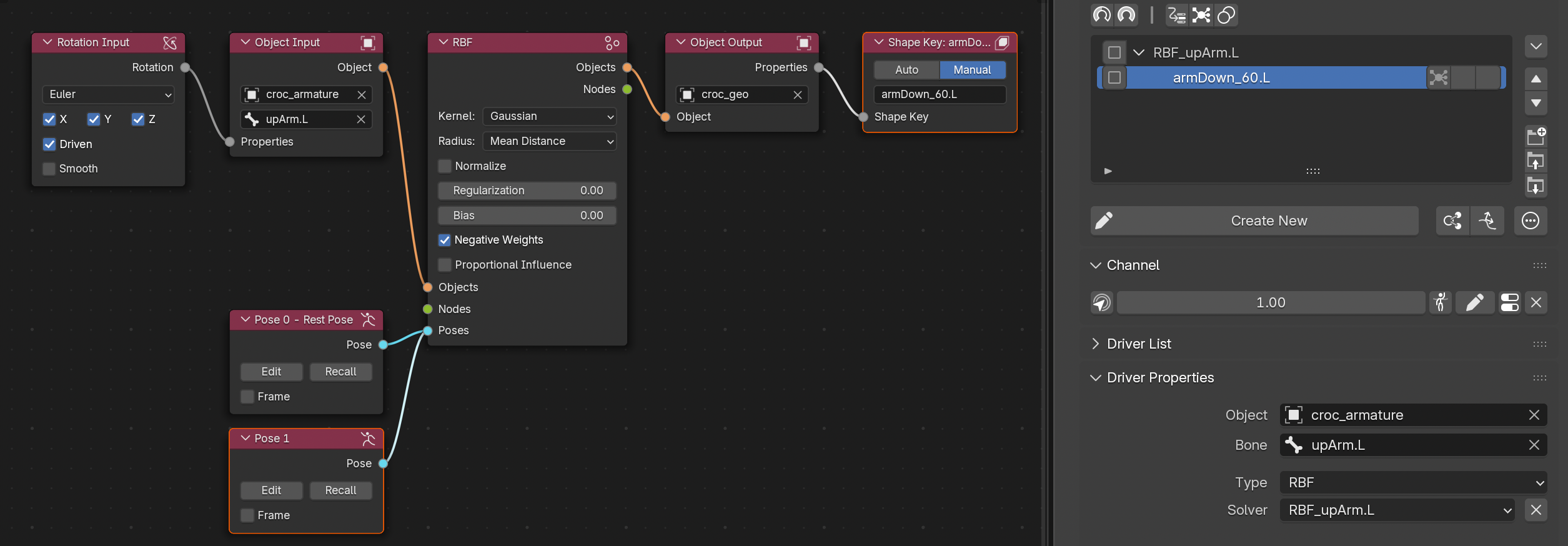
7.4.5 RBF Setup
RBF Nodes can be accessed by selecting RBF as the current Driver Type in the Driver Properties panel.
Since RBF Nodes is a separate add-on, it must be installed and activated before SHAPES is loaded. If it is not active, SHAPES will not recognize it.
7.4.5.1 Basics
The setup for RBF Nodes differs from a Standard Shape Driver because of how RBF solvers work.
- Standard drivers in SHAPES only support one property, making them simpler to set up.
- RBF solvers require an explicitly defined rest pose, used as the basis for interpolation.
7.4.5.2 Input Properties
When a driving object and bone are selected, Input Properties are set automatically based on object type and function. These determine which input nodes and settings are generated when creating the solver.
- Input Properties are adjustable before solver creation but remain read-only afterwards.
- Their purpose is to provide information on the inputs used by the solver.
7.4.5.2.1 Automatic Input Property Setup
The following checks are performed to determine relevant Input Properties:
- If the object or bone is driven by a constraint, transformation properties affected by the constraint are assumed as RBF inputs. Only commonly used constraints are considered.
- If no constraint is present, driver expressions are examined.
-
If neither applies, defaults are set:
- Objects: Location
- Bones: Rotation, with mode taken from the bone’s current rotation mode.
If a constraint or expression is used, the Driven option must be enabled for the respective input. This ensures that the RBF considers both local and driven values. See the RBF Nodes documentation for details.
7.4.5.2.2 Changing Input Property Requirements
If input properties need to be changed after solver creation, it is generally safer to delete the solver and set up a new one. While manual changes are possible, they can introduce errors because Input Properties are stored and referenced in existing pose nodes.
7.4.5.3 Control Object
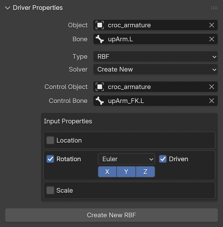
A Control Object (and Bone) can be defined in addition to the Driver Object. This provides workflow flexibility in rigs where deformation bones are indirectly controlled by constraints or other systems.
For example:
- An arm rig may be driven by FK or IK controls, but the deformation bones are constrained.
- The deform bone serves as the RBF driver, but cannot assume poses directly without its controlling elements.
- Defining a Control Object allows forcing the deform bone into the correct pose for RBF setup.
Defining a Control Object is optional and has no effect on solver calculation. It only improves workflow efficiency.
7.4.5.4 Rest Pose
Before creating a solver, the driver must be in its rest pose. This pose serves as a reference for all interpolation.
An incorrectly set rest pose is a common cause of malfunctioning RBF solvers.
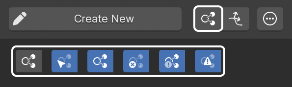
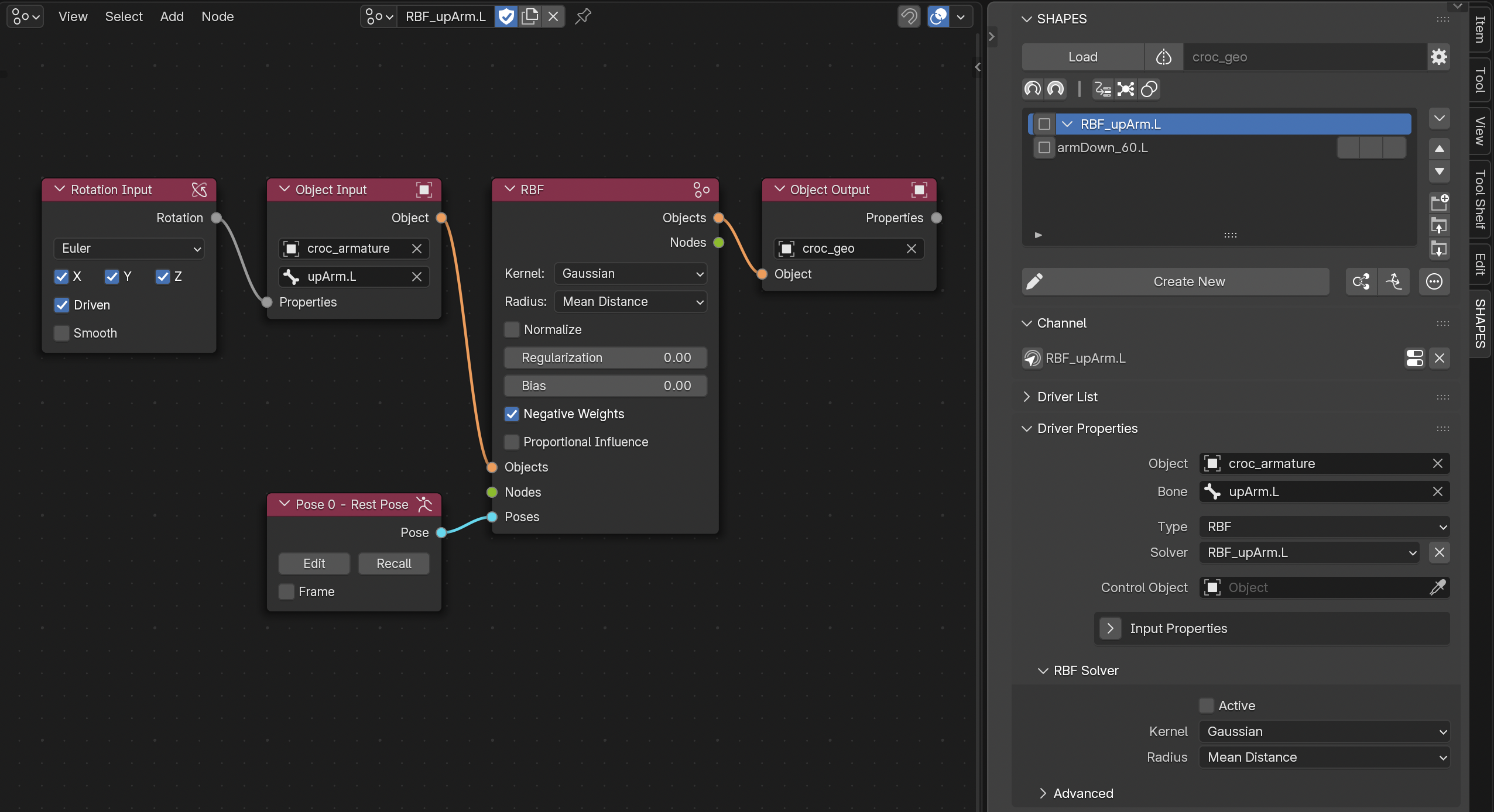
7.4.5.5 Creating a New RBF Solver
With the Input Properties defined and the driver in its rest pose, a new RBF solver can be created.
- Select Create New from the Solver menu.
- Press Create New RBF to generate a new solver with its own RBF Nodes tree.
- The node tree is named after the driver. If the RBF Node Editor is open, it loads automatically.
- A new group item is created in the Target List, also named after the driver, to hold related targets.
7.4.5.6 Solver Menu
The Solver drop-down menu lists all RBF solvers created within SHAPES. Selecting one loads its properties for editing or adding targets.
Only solvers created via SHAPES are displayed.
7.4.5.7 Poses
An RBF solver blends between poses defined by input properties.
-
At minimum, two poses are required: a rest pose and a target pose.
-
While a simple two-pose setup could be achieved without an RBF, solvers are most effective when multiple poses and multi-axis inputs are involved.
7.4.5.7.1 Adding a New Pose
Before assigning an existing pose shape to the current RBF solver, the Driver Object must be in the designated pose. As with creating a new solver from the rest pose, the input property data defining the pose is captured along with the target item’s value. It is therefore essential that the driver is in the correct pose and that the target item has the intended activation value.
To create a new pose:
- Place the driver in the target pose.
- Set the value of the target item (e.g., 1.0 for a shape key). Only required if Auto Set RBF Values is disabled.
- Press the first (input) button of the target item in the Target List to assign the pose.
When Auto Set RBF Values is enabled in the Shape Driver section of the Tool Preferences, the values of all RBF-related target items are set automatically, simplifying the pose creation process.
Assigning a pose will:
- Add an RBF icon to the input button (greyed if inactive).
- Place the target item in the RBF group.
- Add two nodes to the RBF Nodes tree: one for the new pose, one for outputs.
7.4.5.7.2 Creating a New Pose
After the solver has been set up and the base shapes have been assigned, the actual RBF interpolation can be validated. The way the interpolation is performed depends on various factors, such as the number of poses, their placement and distribution, as well as the RBF kernel and its settings. The actual shape of the shape keys also plays a significant role. Usually, it is difficult to predict the final interpolation result in advance when modeling the shapes, and only the activated solver can show if everything works well together.
When reviewing the final interpolation result, it may become obvious that additional poses are required to polish the combined deformation. But simply adding a new pose always affects the current RBF result, which can be a combination of several shapes with various values, and adding a new pose will usually reset all other contributions. This complicates the creation of new shapes that need to fit nicely between existing poses.
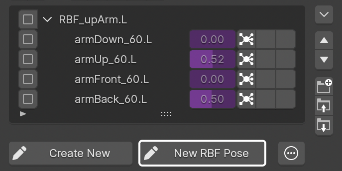
To help with creating and inserting new poses into an existing setup, a second button is available to enter Edit Mode whenever a target item that is part of an RBF solver is selected.
When entering Edit Mode with New RBF Pose, the current contribution of the other shapes of the active RBF solver is taken into account to create the shape for the new pose.
When leaving Edit Mode, the new shape will be automatically added as a new pose to the solver.
7.4.5.7.3 Recall RBF Pose
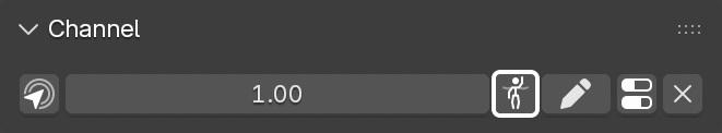
When a target item belonging to an RBF solver is selected, the Channel panel displays an additional button next to the channel value.
Pressing it recalls the stored pose, applying transformations to both the Driver and, if defined, the Control Object.
7.4.5.7.4 Deleting a Pose
To remove a pose:
- Press the first (input) button of the target item in the Target List.
- Confirm deletion.
The target item remains in the list but is no longer linked to the solver.
7.4.5.7.5 Disabling a Pose
When a pose is enabled (the default), it contributes to the RBF solution like any other. When disabled, the pose is removed from the calculation entirely; the solver behaves as if it were never created, and the remaining poses are re-solved without it. Toggling Enable triggers an automatic re-solve, so changes take effect immediately.
Use it to test how a setup behaves with a pose taken out, or to keep an in-progress pose in the tree without having it affect the result. Note that removing a pose this way changes how the neighboring poses interpolate, since the solution is rebuilt over the remaining set.
7.4.5.8 RBF Activation
To begin RBF interpolation with the assigned poses, the solver must be activated. Activation is not automated because the typical workflow requires assigning all poses first and then enabling the solver. This sequence serves as a safety feature to prevent unnecessary computation warnings caused by improperly set poses.
To activate the solver once all poses are assigned:
- Enable the Active checkbox in the RBF Solver panel.
- Active solvers display with a green background in the RBF Nodes Editor.
- If activation fails, a warning icon appears next to the Active checkbox, and the solver node displays a red background.
For troubleshooting a failing RBF calculation, refer to the Troubleshooting section of the RBF Nodes documentation.
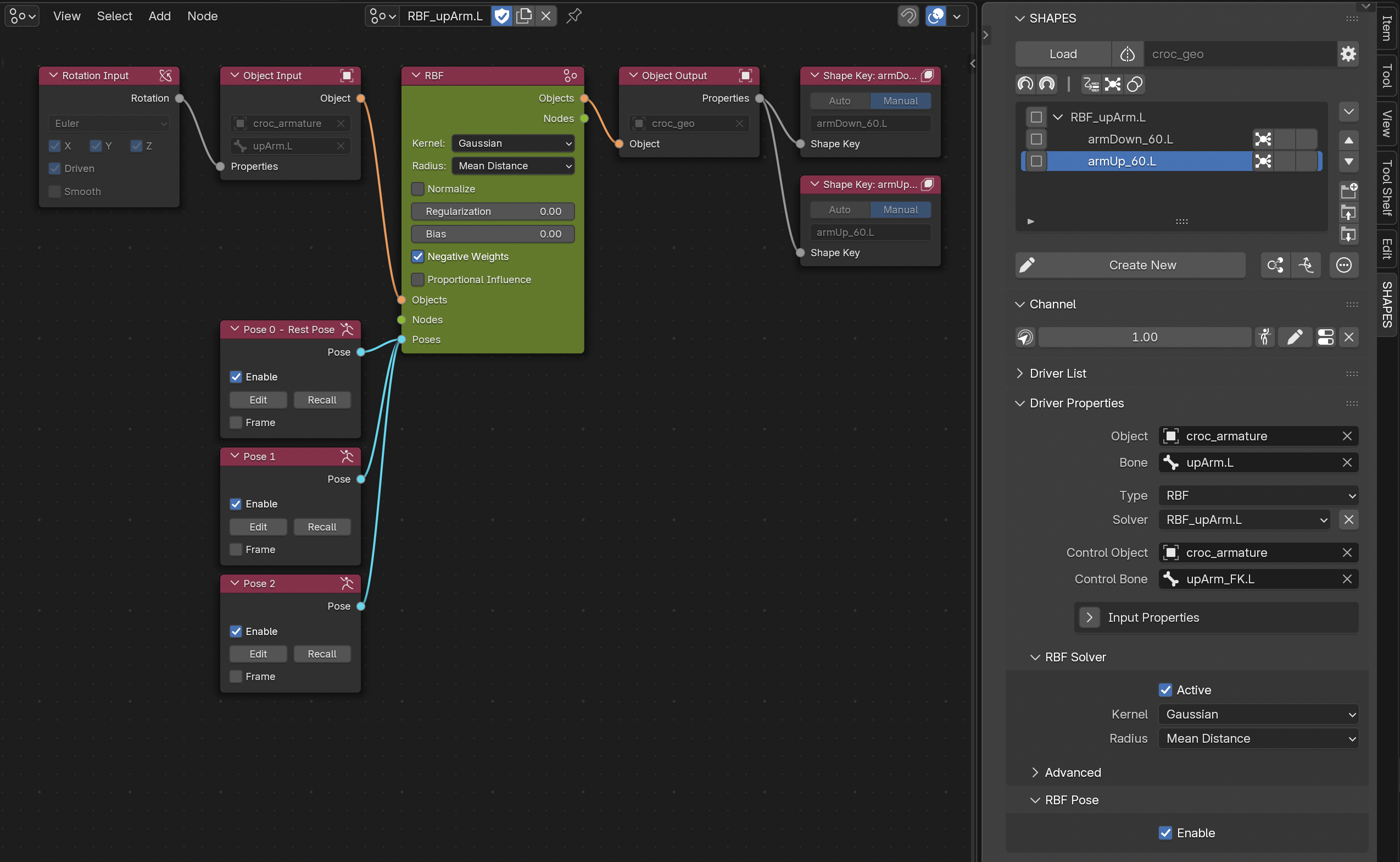
7.4.5.9 RBF Solver Properties
Solver properties are available in the RBF Solver panel and Advanced subpanel. These directly reflect node settings and apply immediately.
For details, refer to the RBF Settings section of the RBF Nodes documentation.
7.4.5.10 Deleting the Solver
To delete a solver:
- Press Delete RBF next to the Solver menu.
- Confirm deletion.
This will:
- Remove all driving relationships (if active).
- Rename the node group with a ‘deleted’ suffix.
- Remove the group item from the Target List.
- Keep all target items in the list, unlinked.
When deleting the group item of an RBF setup, the associated solver is removed as well.
7.4.5.11 Create Opposite RBF
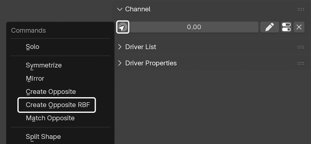
RBF setups often require mirrored versions for the opposite side of a rig. Manual mirroring can be complex due to the number of poses and dependencies.
SHAPES provides an operator in the Channel Commands Menu to create a mirrored solver automatically.
Create Opposite RBF:
- Duplicates all target items in the RBF Nodes setup.
- Mirrors driver and control object transformations.
- Creates a fully mirrored solver setup in one step.
8. Combos
When working with shape keys and corrective shapes, Combos play an important role whenever multiple shapes are activated simultaneously. Even carefully crafted shapes can interact in ways that produce unexpected results. In these cases, it becomes necessary to create additional shapes that correct problematic deformations caused by the overlap of two or more shapes. These corrective combination shapes are called Combos.
Because Combos consist of source shapes (drivers) and a controlled shape (target), the participating items are referred to as Combo Drivers and Combo Targets.
A Target List item can serve as a driver for multiple Combos, while a Combo target can only be controlled by a single Combo.
8.1 Combo Setup
Combos are set up directly through the Target List:
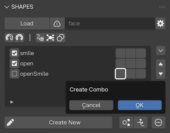
- Select all items that should act as Combo drivers. A Combo requires at least two drivers.
- On the list item that will act as the Combo target, press either the first (inputs) or the second (outputs) button.
- Confirm the Combo creation in the dialog.
The Combo target is now driven by a driver that uses the selected Combo drivers as its input.
By default, a standard Combo multiplies the values of its drivers. The Combo target only reaches a value of 1.0 if all drivers are at 1.0.
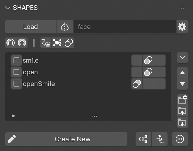
8.2 Combo List Display
When a Combo is created, all participating items receive an icon that indicates their function:
Combo Driver
All Combo driver items are marked with a Combo-driver icon in the second column of the item’s button row. This indicates that the item is used as a driver. If one or more drivers already drive other Combos, the icon displays an additional “+” to show multi-use.
Combo Target
The Combo target item is marked with a Combo-target icon in the first column of the button row. This shows that the item is driven by a Combo. A target item can only belong to one Combo.
8.3 Combo Info Panel
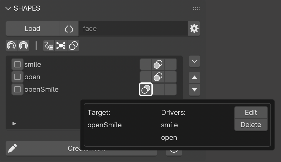
The details of a Combo can be viewed by pressing one of its Combo buttons in the Target List. This opens a floating panel containing all related information:
Combo Driver
Pressing the Combo button on a driver displays all Combo targets the selected driver contributes to. It also lists any other shapes acting as co-drivers in those Combos. Each Combo is shown in its own section of the panel.
Combo Target
Pressing the Combo button on a target displays all drivers that contribute to the Combo.
8.4 Edit Combo
Active Combos can be edited to add or remove drivers, change the Combo target, or modify how driver values are combined into a driving value. All changes are interactive.
To edit a Combo:
- Press the Combo button on either a driver or target item.
- In the Info panel, choose Edit from the according Combo entry.
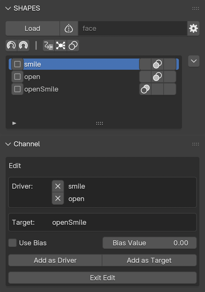
This switches SHAPES into Combo Edit Mode. All edit controls are available in the Channel panel while Combo Edit Mode is active.
The panel shows which items are currently acting as drivers and which item is targeted.
Editing options include:
-
Remove Driver
Remove a driver by pressing the X button next to its entry. Since a Combo requires at least two drivers, the last two drivers cannot be removed. To replace a driver in a double-Combo, first add the new driver, then remove the old one. -
Add Driver
Select the item in the list and press Add as Driver to include it in the Combo. -
Add Target
Select the item in the list and press Add as Target. The new item directly replaces the current Combo target.
To exit Combo Edit Mode, press the Exit Edit button.
8.5 Combo Bias
By default, Combo evaluation is performed by multiplying all driver values. This simple method is sufficient for most cases, especially for double-Combos (two drivers).
However, for Combos with three or more drivers (triples, quads, etc.), multiplication can lead to overly small results. For example, three drivers at 0.5 each result in a target value of 0.125 (0.5 × 0.5 × 0.5), which may be too weak.
An alternative is to compute the geometric mean of the input values, which produces stronger results. Yet, because animation and deformation depend on visual appearance rather than pure mathematics, even the geometric mean can sometimes feel too strong.
To provide artistic control, SHAPES introduces a Bias property. Bias adjusts the way driver values influence the target, allowing smoother or sharper activations depending on the desired effect.
Bias is only available in Combo Edit Mode.
- Enable Use Bias to activate exponent compensation.
- Adjust the Bias Value to control how quickly or slowly the Combo activates in response to driver values. Changes are visible interactively when drivers are not fully activated. The bias works by modifying the exponent in the evaluation equation.
Example:
Assume three drivers, each at 0.5.
Without Bias (geometric mean):
combo_value = pow((0.5 * 0.5 * 0.5), (1 / 3)) ≈ 0.5
With Bias = +0.2 (faster activation):
combo_value = pow(0.125, (1 / 3 + 0.2)) ≈ 0.57
With Bias = -0.2 (slower activation):
combo_value = pow(0.125, (1 / 3 - 0.2)) ≈ 0.42
This demonstrates how positive Bias values push Combos toward stronger activation earlier, while negative Bias values hold them back until driver values are higher.
8.6 Delete Combo
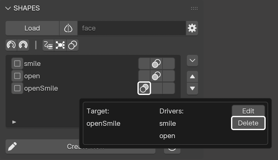
To delete a Combo, press the Combo button on either a driver or the target in the Target List. In the Info panel, locate the Combo entry and press Delete. This immediately removes the Combo.
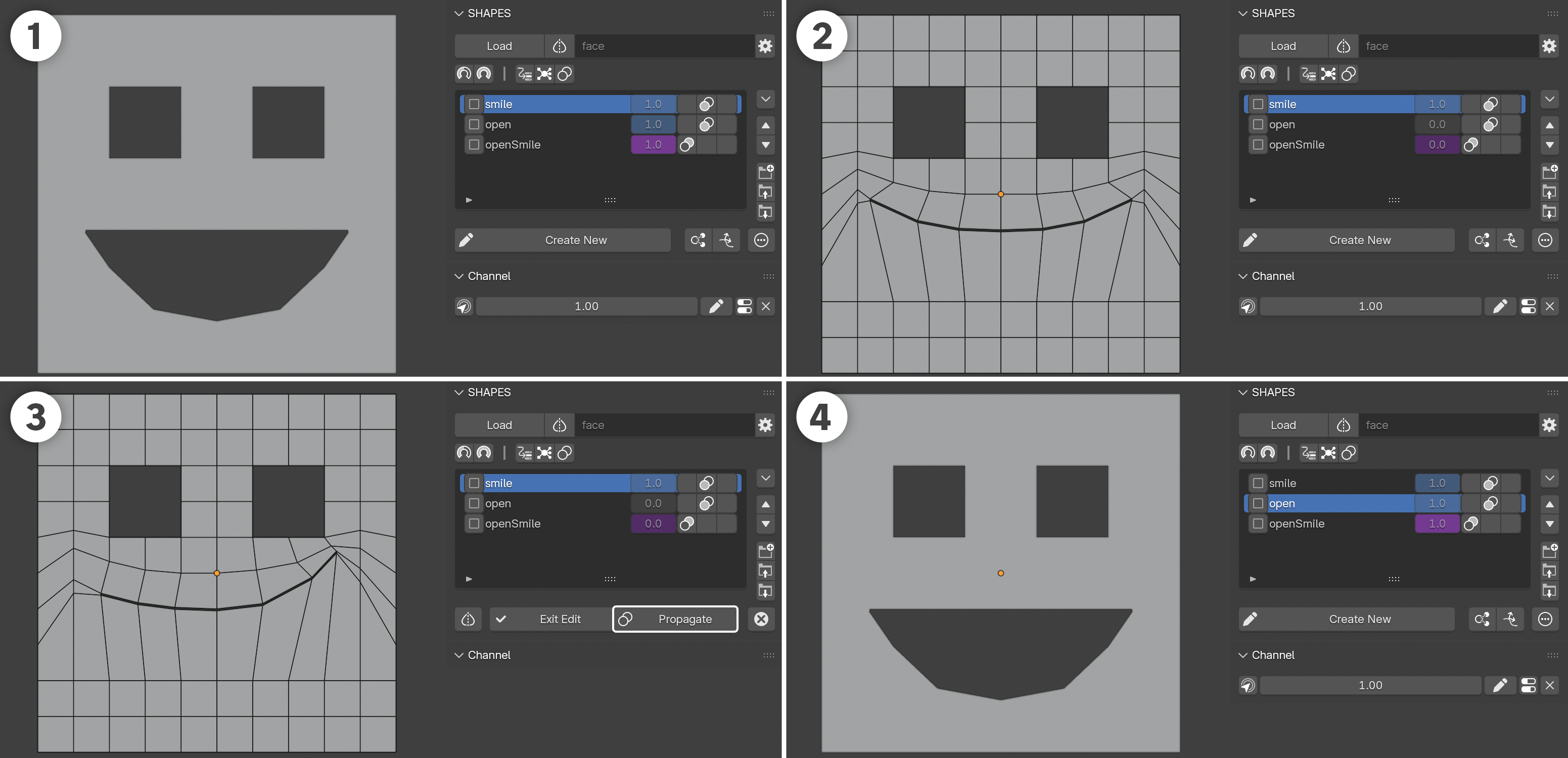
8.7 Combo Edit Propagation
Combos are often used to fix artifacts that occur when multiple shapes are active together. A Combo is valid only as long as the driving shapes remain unchanged. If a driver shape is later edited, the Combo shape usually also needs refinement, since its result depends on the drivers.
To reduce this extra work, SHAPES provides Edit Propagation. This feature automatically propagates edits made to a driver downstream into its dependent Combo shapes. The result is less manual cleanup and more consistent deformations.
Propagation cannot guarantee perfect results in all cases. Manual verification is recommended to ensure no unintended influences appear in the Combo targets after editing a source shape.
Propagation workflow:
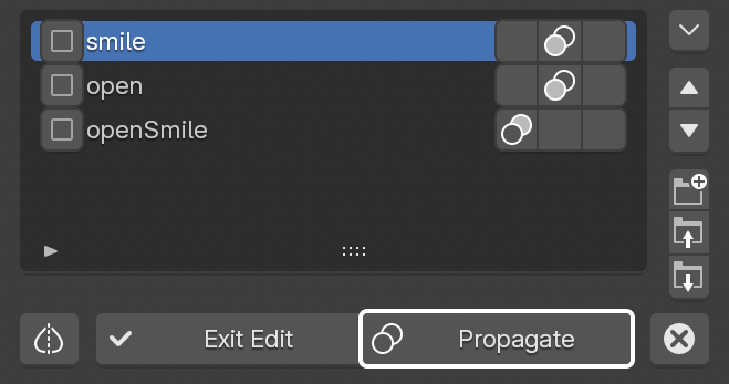
- When editing a shape that serves as a Combo driver, an additional Propagate button appears next to Exit Edit.
-
This gives two options when finishing the edit:
-
Exit without propagation
Only the edited shape is updated. Combo targets remain unchanged. -
Exit with propagation:
The edited shape is updated and the difference between the edited and original driver shape is automatically applied to the dependent Combo targets. This ensures that Combo results remain consistent even if a driver shape has been modified.
-
Exit without propagation
9. Influence Map
The Influence Map feature in SHAPES simplifies the process of dividing a complex shape into multiple sub-shapes using vertex groups.
9.1 Breaking Down Complex Shapes
In production workflows, complex facial or deformation shapes are often divided into smaller, localized sub-shapes to achieve greater precision and control. A single sculpted expression can include several regions of motion, such as lips, cheeks, and eyelids, that need to be adjusted or combined independently during animation. Separating these regions into individual sub-shapes allows each area to be edited, reused, and blended without affecting unrelated parts of the mesh.
This modular approach improves flexibility in corrective workflows, simplifies shape reuse across different expressions, and reduces inter-shape conflicts that typically occur when broad deformations overlap. It also enables artists to refine or rebuild specific regions without resculpting the entire expression.
Breaking down complex shapes is therefore a key step in production environments that rely on sculpted expression libraries or key-shape-based rigs, ensuring clean articulation, predictable results, and efficient iteration during both rig development and animation.
9.2 Overview
Influence Maps provide a structured method for decomposing complex sculpted shapes into manageable sub-shapes. Each Influence Map uses an auxiliary armature bound to a duplicate of the mesh, with each bone representing a distinct sub-region of the overall deformation. These regions are defined through vertex weight painting in a familiar workflow. Because the weights can be normalized, no overlap occurs between the resulting sub-shapes, ensuring clean separation and predictable blending behavior.
Once the weighting process is complete, the vertex groups are transferred back to the original shape-key setup, and the auxiliary object is removed. The complex source shape is automatically duplicated and assigned according to the defined regions, producing a consistent set of sub-shapes that can later be reconstructed or refined based on the stored Influence Map data.
This approach simplifies the management of detailed shape libraries, maintains precise deformation control, and supports an iterative workflow suited to production environments where complex sculpted expressions must be divided into reusable, non-overlapping components.
Main features:
- Vertex groups are normalized to each other to guarantee a full reconstruction of the source shape without additive overlaps.
- Editing vertex groups and previewing the result can be synchronized to immediately show the effect while adjusting weight assignments.
- Vertex groups are associated with the resulting sub-shapes, aiding identification.
- For refinement, the Influence Map can be edited in a few steps without the need to manually locate and select shape keys or related vertex groups.
9.3 Influence Map Setup
Because the Influence Map is essentially a process of splitting a shape key into several sub-shapes using vertex groups, any shape key can serve as the source for the setup.
The only important step is to define the names of the resulting regions before creating the setup. These names will be used to identify the regions during the painting process and to name the corresponding vertex groups.
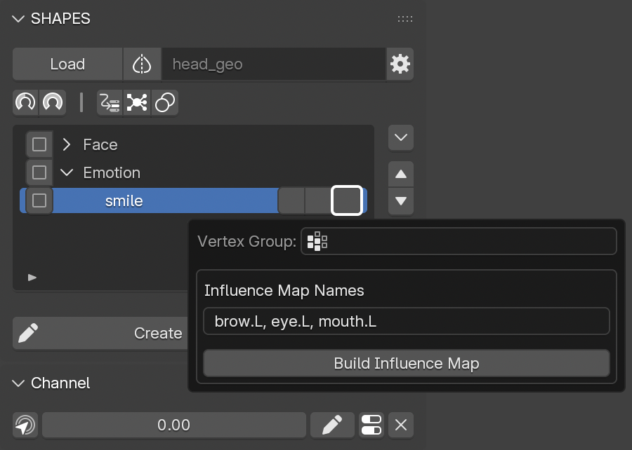
To setup the Influence Map:
- Press the third (vertex group) button of the target shape to process.
-
In the
Influence Map Names
field, enter all names to identify the sub-shapes of the
Influence Map. The list of names must be comma-separated.
-
If regions are to be split into left and right sides, only one side identifier is required.
For example:
brow.L, eye.L, mouth.L
will automatically result in brow.L, brow.R, eye.L, eye.R, mouth.L, mouth.R.
-
If regions are to be split into left and right sides, only one side identifier is required.
- Press Build Influence Map.
Although it is possible to rename the resulting shape keys and vertex groups, it is recommended to keep the generated names to ensure that rebuilding an Influence Map setup can be performed without issues.
This creates the Influence Map Builder Setup, consisting of:
- A copy of the undeformed mesh for painting influence regions alongside the deformed mesh.
- An armature bound to the copied mesh, with a bone for each influence region.
- An additional Base bone that holds all weights when no assignments exist.
- The armature and mesh positioned along the negative X-axis, based on the mesh bounding box. If the armature is moved, its position is stored for later editing sessions.
- The mesh switched to Weight Paint Mode.
- Auto Normalize enabled in the Weight Paint Tool Options to prevent visual overlap between regions.
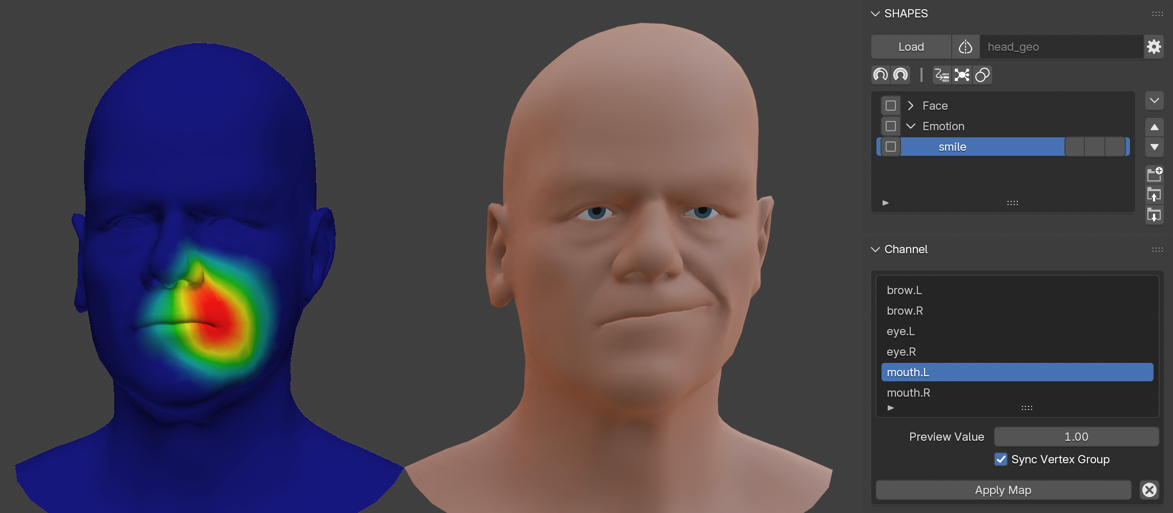
9.4 Influence Map Painting
The painting process for the Influence Map follows the same principles as standard weight painting. Because this is a guided workflow, SHAPES provides several controls to keep the process transparent.
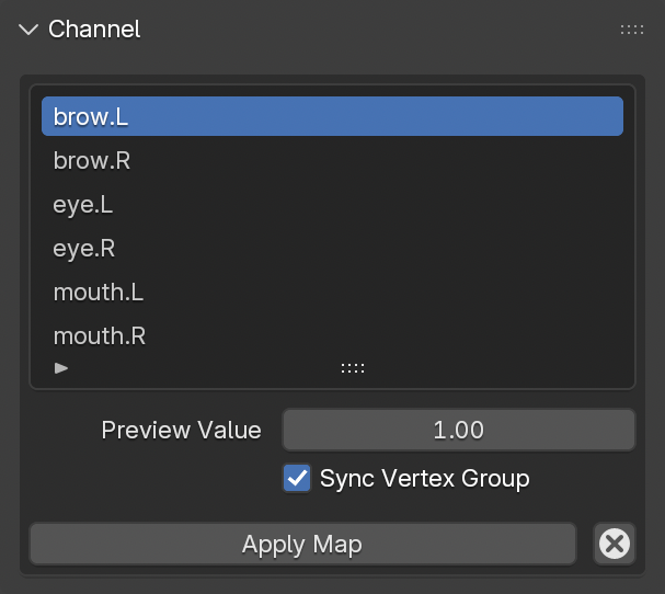
Influence Map List
Displays all defined regions with their respective names. Selecting an item switches the preview to that region. The strength of the previewed shape is controlled by the
Preview Value.
If
Sync Vertex Group
is enabled (default), switching regions also changes the active vertex group associated with that region and shape. This allows seamless switching between adjoining regions for fine-tuning the blending.
Preview Value
Controls the intensity of the currently previewed shape affected by the corresponding weight map.
After the initial setup, no shapes are previewed because all weights are assigned to the
Base
bone until individual regions receive painted weights.
Sync Vertex Group
When enabled, selecting a different region in the list also switches the active vertex group for painting.
When disabled, changing the region affects only the previewed shape, not the active vertex group.
This is useful for visualizing how the current vertex group influences neighboring shapes.
9.4.1 First Steps After Creating the Initial Influence Map Setup
- Select the region in the list to begin assigning weights.
- Paint weights for this region as in any other armature-based workflow.
- If the shape differs from the undeformed mesh in this region, the result becomes immediately visible.
- Adjust the Preview Value to observe the effect of the partial shape blending in and out.
9.5 Applying the Influence Map
Once all regions of the Influence Map have been painted, the setup must be transferred to the deformed model as individual shape keys.
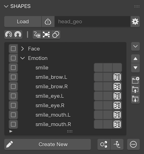
Press Apply Map to:
- Create duplicates of the source shape key below it in the Target List.
- Name each new shape key using a combination of the source shape key and the region name.
- Normalize and transfer painted weights from the armature as vertex groups to the corresponding shape keys.
- Assign vertex group names based on the source shape key and region.
- Mark resulting sub-shapes in the Target List with distinct icons identifying them as Influence Map regions.
- Delete the duplicated mesh and armature after transfer.
Although it is possible to rename the resulting shape keys and vertex groups, it is recommended to keep the generated names to ensure that rebuilding an Influence Map setup can be performed without issues.
9.6 Cancelling the Influence Map Setup
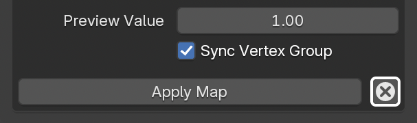
To cancel the setup, press Cancel, located next to the Apply Map button.
9.7 Editing the Influence Map
To edit an existing Influence Map for refinement:
- Press the third (vertex group) button of any related sub-shape.
- From the panel, select Edit Map.
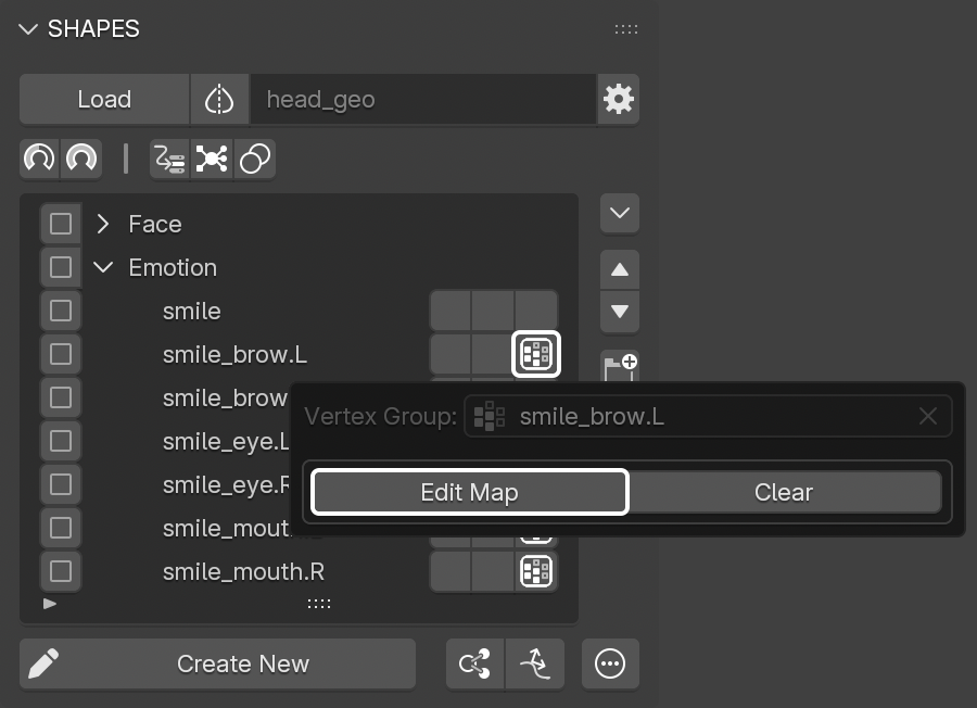
This re-creates the Influence Map Builder Setup and transfers the vertex groups of the individual regions to the armature for further painting.
9.8 Adding a New Region to an Influence Map
To add new regions, the additional names must first be registered with the Influence Map.
To add a new region:
- Press the third (vertex group) button of the source shape key in the Target List.
- Add the new region names to the comma-separated list in Influence Map Names.
- Press the third (vertex group) button of any sub-shape item in the Target List.
- Select Edit Map to rebuild the Influence Map setup for weight painting.
New bones for the added regions are included in the setup with their weights assigned to the
Base
bone.
Painting can continue as usual.
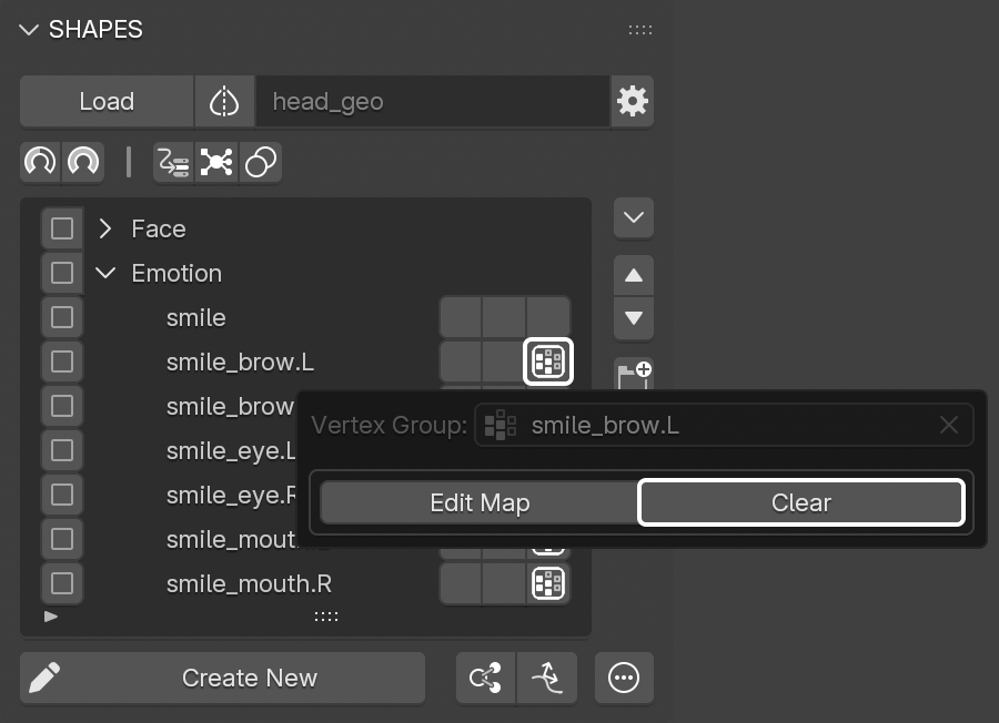
9.9 Clearing the Influence Map Assignment
If a shape key in the Target List has a vertex group associated with an Influence Map, it cannot be edited directly via the third (vertex group) button. The assignment is managed by the Influence Map.
To remove this link, press Clear in the panel.
This removes the vertex group assignment and disassociates the shape key from the Influence Map.
10. Vertex Groups
An essential part of building a shape key setup is creating and editing weight maps to fine-tune or limit the influence of specific shape keys.
To streamline this process, SHAPES provides a set of tools to quickly create or edit weighted influences for the currently selected shape key item in the Target List, without the need to manually assign or locate the corresponding vertex group.
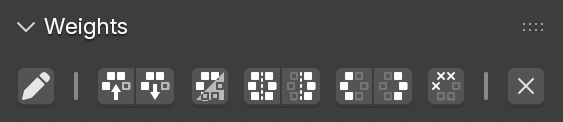
The Weights panel contains a set of operator buttons to access commonly used tools when working with vertex group-based weighting. This can be especially helpful because these tools do not require switching to Weight Paint Mode.
10.1 Edit
Pressing the Edit button for a shape key item in the Target List either creates a new vertex group and assigns it to this shape key, or edits the existing one.
The vertex group is then set as active, and the mesh switches to Weight Paint Mode.
Switching to Weight Paint Mode also disables Paint Mask and Vertex Selection.
10.2 Copy
Copies the vertex group data from the currently selected shape key item in the Target List.
If the mesh is in Edit Mode and has an active vertex selection, only the weights of the selected vertices are copied.
10.3 Paste
Applies the previously copied vertex group data to the current selection.
It works on either the currently selected shape key or all shape keys that have their checkboxes enabled.
10.4 Invert
Inverts the vertex group data assigned to the current selection.
It works on either the currently selected shape key or all shape keys that have their checkboxes enabled.
If the mesh is in Edit Mode and has an active vertex selection, only the selected vertices are inverted.
10.5 Symmetrize
Makes the vertex group symmetrical so that both sides are identical.
It works on either the currently selected shape key or all shape keys that have their checkboxes enabled.
If the mesh is in Edit Mode and has an active vertex selection, only the selected vertices are symmetrized.
This operator is only available if a Symmetry Map has been set up for the loaded object.
10.6 Mirror
Mirrors or flips the vertex group in place, so that the weights on one side appear on the other side.
It works on either the currently selected shape key or all shape keys that have their checkboxes enabled.
If the mesh is in Edit Mode and has an active vertex selection, only the selected vertices are mirrored.
This operator is only available if a Symmetry Map has been set up for the loaded object.
10.7 Trim
Trims the weight values on either side of the mesh so that no weights remain on that side. This is helpful to ensure that no weights cross the line of symmetry.
It works on either the currently selected shape key or all shape keys that have their checkboxes enabled.
If the mesh is in Edit Mode and has an active vertex selection, only the selected vertices are trimmed.
This operator is only available if a Symmetry Map has been set up for the loaded object.
10.8 Bake
Applies (bakes) the vertex group weights to the shape key data and removes the vertex group assignment from the shape key. The vertex group is also deleted from the object.
It works on either the currently selected shape key or all shape keys that have their checkboxes enabled.
10.9 Remove
Removes the vertex group assignment from the shape key. The vertex group is also deleted from the object.
In the case of an
Influence Map, all associated data is removed.
This is equivalent to
Clearing the Influence Map Assignment
It works on either the currently selected shape key or all shape keys that have their checkboxes enabled.
11. Organisation
SHAPES allows extensive organisation of shape keys through the Target List.
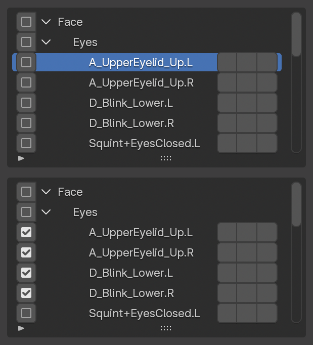
11.1 Selection
Because Blender’s custom list UI has limitations regarding multi-selection, SHAPES provides two distinct ways to select items for actions:
- Single Selection: Clicking on a list item selects it as the active shape key or group for editing.
- Multi Selection: Each item has a checkbox for enabling or disabling selection. This method is used for performing multi-item actions.
11.2 Target List Button Stack
A vertical stack of buttons to the right of the Target List provides tools for organising and managing items.
Operators for organising the Target List, such as group creation, parenting, or reordering, are unavailable while a search or filter is active.
Available controls include:
Target List Menu
Opens a popup menu with advanced operations:
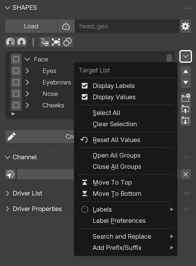
- Display Labels: Shows label colors in the list.
- Display Values: Adds a value field for the shape keys in the list. The value is read-only and cannot be edited directly. To make changes, the shape key must be selected so it appears in the Channel section.
- Select All: Enables selection for all items.
- Clear Selection: Disables selection for all items.
- Reset All Values: Resets all channels to zero, except for channels controlled by drivers where the active driver prevents manual adjustment.
- Open All Groups: Expands all groups to reveal their contents.
- Close All Groups: Collapses all group entries.
- Move To Top/Bottom: Moves the selected item(s) to the top or bottom of the hierarchy.
- Labels: Opens a list of available colors to assign a label to the selected list items for visual identification. Press Clear Label to remove the current label.
- Label Preferences: Opens a panel to customize label colors and their descriptions. See Label Preferences for more information.
- Search and Replace: Replaces strings in selected items. Multiple search terms can be combined using +, e.g. left+arm+leg.
- Prefix/Suffix: Adds a prefix and/or suffix to item names, either for the selected item or all selected items.

Move Item Up/Down
Moves the selected item(s) one position up or down.
Add Shape Group
Adds a new group to the
Target List.
- If only one shape key is selected, the group is added above it for easy assignment.
- If multiple items are selected via checkboxes, they are automatically added to the new group.
Parent to Group
Assigns selected items to a group. This depends on the selection method:
- If using single selection, the item directly below the group is added to it.
- If using checkbox selection, selected items are added to the currently selected group.
Remove from Group
Removes the selected item(s) from their current group assignment.
11.3 Label Preferences
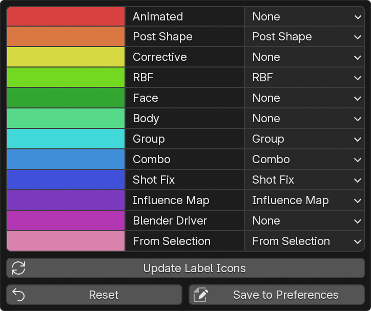
This panel provides access to customizing:
- Label colors
- Descriptions
- Automatic assignments
Labels are stored in the scene so that each file can maintain its own label configuration. This allows different label setups to be used per scene, which can be useful for different workflows and also makes it possible to share scenes without depending on local preference settings.
Labels with a generic description (e.g., “Label xx”) are hidden from the assignment and filtering menus. Removing a description resets it to a generic label name.
Auto Assign
The Auto Assign menu allows labels to be assigned automatically to specific list items when they are created. The available types correspond to the different item types created by SHAPES.
For example, if a label is configured with the auto-assign type Group, all newly created groups automatically receive that label.
The From Selection type applies to shape key items created from the current scene selection using either Add Selection as Shape or Add Selection as Posed Shape.
Setting Auto Assign to None disables automatic assignment for the label.
Update Label Icons
Regenerates the icon set to reflect updated label colors during assignment and filtering after a color change.
Reset
Resets label colors and descriptions to their default values.
Save to Preferences
Saves the current label configuration to the local preferences. This makes it possible to store a customized label scheme independently of the default settings. The saved configuration is used automatically for newly created scenes.
11.4 Filter
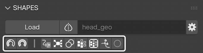
Working with many shape keys in a setup can become challenging, especially when dealing with various drivers and dependencies. While organisation helps, it may still be difficult to locate items that require attention.
Filters provide an additional way to narrow focus to specific parts of a setup, particularly when working on certain poses. SHAPES offers several filter options to limit the visible list items based on their current state.
Operators for organising the Target List, such as group creation, parenting, or reordering, are unavailable while a search or filter is active.
Active Values
Displays only items with an active shape key value greater than zero. If an item is nested within a hierarchy, the full hierarchy will be expanded for visibility.
Maximum Values
Displays only items currently set to their maximum value (i.e., a shape key value of 1). Hierarchies containing those items will be fully expanded.
Shape Driver
Displays only items that are controlled by a shape driver.
RBF Nodes
Displays only items that are controlled by a
RBF Nodes
solver.
Combos
Displays only items that participate in a Combo, either as source or target.
Vertex Groups
Displays only items with an assigned vertex group.
Influence Maps
Displays only items that are part of an
Influence Map.
Post Deformation Shapes
Displays only post deformation shape key items.
Label
Opens a menu to select a label used to filter list items. To clear the filter, select the active label again or choose Clear Label.
The current expanded or collapsed state of groups is saved before entering filter mode. When all filters are disabled, the previous group state is restored.
12. Symmetry Map
When working with character rigs and shape keys, mirroring is essential for accelerating various processes and improving the overall workflow. Especially when working with shape keys, it is crucial to symmetrize a shape or recent edits, or to flip a shape to create the opposite side of the setup.
However, while mirroring is straightforward for simple, perfectly symmetrical meshes, it can easily fail if the mesh is not completely symmetrical to begin with. Even with topological symmetry, there is no guarantee that mirroring will function reliably in all cases. Additionally, if a mesh consists of multiple mesh islands, most mirroring methods fail, as they generally expect only a single island.
SHAPES employs a built-in Symmetry Map, which supports both position-based and topological symmetry. It is capable of handling a wide range of symmetrical meshes, including those with multiple islands. The mapping is performed once when loading the mesh for the first time and is then used for various symmetry operations. This means that with dense meshes, the initial loading and evaluation may cause a slight delay, but with the advantage that subsequent mirroring operations will be fast and reliable.
12.1 Status
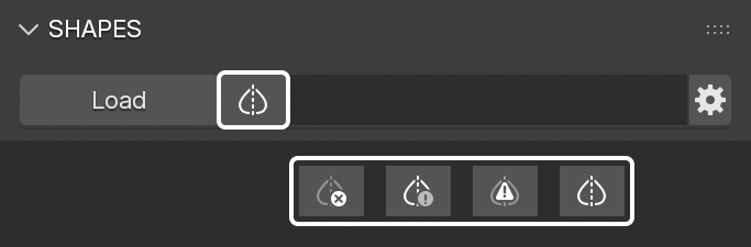
The Symmetry Map status is indicated next to the Load button. The icon represents one of the following states:
- Inactive Symmetry with no mapped vertices
- Undefined Symmetry due to missing data
- Partial Symmetry with only portions mapped
- Mismatch indicating that the number of vertices differs from the stored map data
- Active Symmetry with a complete mapping
12.2 Preferences
The mapping process relies on two preference settings, found in the Tool Preferences .
The properties are not shown in advance, but only after the mesh has been loaded. They are also not global add-on preferences but are properties owned by the active mesh object.
12.3 Menu
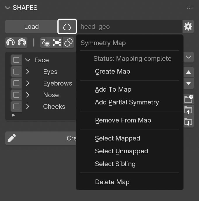
The Symmetry Mapping indicator also provides access to the menu for manually setting up and editing the Symmetry Map.
12.3.1 Create Map
Starts the automatic mapping process and evaluates the mesh. All verified islands are mapped and stored in the symmetry map on the mesh. If the mesh is in
Object Mode, all islands are mapped automatically. If the mesh is in
Edit Mode, the currently selected edge is used as the user-defined center edge to map the related island.
Only a single edge selection is supported.
Map creation is also performed automatically when loading a mesh for the first time, provided the Tool Preferences setting Auto Create Symmetry Map is enabled.
Create Map can also be used to generate a partial symmetry map in cases where the mesh has mixed topology. Select the faces of the mesh that have topological symmetry and run Create Map.
12.3.2 Add To Map
Adds islands to the symmetry map that failed during the automatic mapping process. There are three types of mesh islands which can be mapped in this way:
-
Spanning Island:
The island has topological symmetry, but the center edge is too far from the mesh center. Select the edge to be used as the center edge and execute Add To Map. -
Spanning Island - no center:
The island may have topological symmetry but lacks a center edge loop. In this case, select two matching edges on either side of the mesh before running the operator. -
Island Pair:
Two islands that are symmetrical to each other on opposite sides of the mesh. Select two matching edges, one from each island, then run the operator.
12.3.3 Add Partial Symmetry
Partial symmetrical meshes generally lack full topological symmetry, meaning they differ on each side of the mesh. Processing and mapping these islands is only possible by matching point positions, and such meshes often cannot be completely mapped. The mapping process attempts to find symmetrical vertices based on their position and the specified tolerance. A lower tolerance might miss valid pairs, while a higher tolerance could identify too many, resulting in failed mapping. A practical approach is to test various tolerance values and compare outcomes.
Partial mapping is also additive: once vertices have been mapped, they are ignored in subsequent passes. This allows multiple consecutive operations with different settings to progressively build the symmetry map.
To further assist partial mapping, it is possible to guide the process with a semi-automatic tolerance. This is done by selecting two matching vertices from both sides of the mesh, ideally from a side view. Their relative offset is used to determine the tolerance for the next operation only. This facilitates extending the map by incrementally mapping vertices with increasing tolerance values.
If a mesh has mixed topology, with some parts being topologically symmetrical and others not, it is possible to guide the mapping process using a custom face selection. This allows partial symmetry to be mapped reliably without relying on positional guessing. Select the faces of the mesh that have topological symmetry and run Create Map.
12.3.4 Remove From Map
In some cases, partial mapping may include vertices that were incorrectly identified as symmetrical counterparts due to their spatial position and the limitations of position-based identification. These vertices may need to be removed manually to avoid mirroring issues.
To remove mismatched vertices, select them in Edit Mode and run Remove From Map.
12.3.5 Additional Operators
Several operators assist in reviewing the current Symmetry Map by selecting vertices directly in the mesh.
-
Select Mapped:
Switches the mesh to Edit Mode and selects all vertices successfully mapped. -
Select Unmapped:
Switches the mesh to Edit Mode and selects all vertices that have no corresponding sibling on the opposite side. -
Select Sibling:
Expands the current vertex selection by also selecting the related sibling vertices on the other side of the mesh. -
Delete Map:
Removes the symmetry map from the mesh.
13. Additional Actions
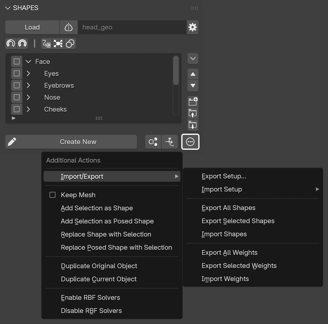
The Additional Actions menu is located below the Target List, to the left of the Create New shape button. It provides access to various tools that can assist when working with shape key setups.
13.1. Import/Export
This submenu contains operators for exporting and importing shape key-related data.
13.1.1 Export Setup
In a character pipeline, it is sometimes necessary to export the full shape key setup, or only parts of it, for reuse or rebuilding after model updates.
Exporting the setup allows detailed control over what data is exported, which elements are included, and what happens to the setup after export.
The export panel includes the following controls:
Mode
- Export Only: Exports the specified data without modifying the setup.
- Delete Drivers and Combos After Export: Exports the specified data and removes all drivers associated with the shape keys. Vertex group assignments are preserved.
- Delete Setup After Export: Deletes the complete setup after export, including all shape keys, drivers, associated vertex groups, and Target List data.
- Rebuild Setup: Deletes the complete setup after export and rebuilds it.
Data Included in Export
- Setup Data: Target List and shape key specific settings.
- Shape Keys: The deltas of all shape keys, equivalent to Export All Shapes.
- Vertex Groups: Vertex groups associated with the shape keys, equivalent to Export All Weights.
- Vertex Groups Links: Information about which vertex groups are assigned to which shape keys.
- Combos: Shape combo data, including combo drivers and targets.
- Drivers: Standard drivers set up outside of SHAPES.
- RBF Nodes: Node group data for all associated RBF Nodes networks.
- Shape Drivers: Drivers created with SHAPES.
- Driver List: The list of driver objects. Disable this to use it as a cleanup function when rebuilding the setup, in case more objects are listed than are actually used. Missing driver objects are added when the driven target item is selected.
The export skips any post-deformation shape key data and Target List items.
The exported data is saved in a subfolder of the specified export path, named after the object.
Example: [export-file-path]/OBJECTNAME
13.1.2 Import Setup
Imports a previously exported shape key setup for the currently loaded object. The submenu lists all setups located at the Export Path specified in the Tool Preferences.
This menu item is only visible when the current object has no setup assigned. Importing a setup onto an object with an existing active setup is not supported.
The selected setup is loaded for the current object if the vertex and polygon count of the object matches the stored data.
Unlike the Maya version of SHAPES, exported setup data is written to a JSON file and is not self-contained, as it includes no executable code and requires SHAPES to be installed and active.
13.1.3 Export All Shapes
This operator exports the selected shape keys to a JSON file, saved in the data folder specified in the Tool Preferences. Only the deltas (i.e., the differences compared to the base shape) are stored, not the full shape key point data.
The exported shapes are saved as a single file within a subfolder of the specified export path.
Example: [export-file-path]/OBJECTNAME/shapes/OBJECTNAME.json
13.1.4 Export Selected Shapes
Similar to Export All Shapes, but exports only the selected shape keys to a JSON file.
13.1.5 Import Shapes
This operator imports shape key data from a JSON file previously generated with the Export Shapes function. It reconstructs the shape keys on the current object, appending a sequence number to any new shape key if a name conflict occurs.
The file name must match the object name exactly and follow the same naming convention as described above.
Example: [export-file-path]/OBJECTNAME/shapes/OBJECTNAME.json
If the file is missing or doesn’t match the required naming pattern, nothing will be imported.
13.1.6 Export All Weights
This operator exports all vertex groups assigned to the object's shape keys to a JSON file, saved in the data folder specified in the Tool Preferences.
The exported vertex groups can be saved either as a single file or as individual files per group within a subfolder of the specified export path. Single files are named after the object, while separate files receive the corresponding vertex group name. See the Separate Weight Maps option in the Tool Preferences.
Example: [export-file-path]/OBJECTNAME/weights/OBJECTNAME.json
13.1.7 Export Selected Weights
Similar to Export All Weights, but exports only the vertex groups of the selected shape keys to a JSON file.
13.1.8 Import Weights
This operator imports vertex group data from a JSON file previously generated with the Export Weights function. If a vertex group already exists, its weights will be replaced with the imported values.
The file name must match the object name exactly and follow the same naming convention as described above.
Example: [export-file-path]/OBJECTNAME/weights/OBJECTNAME.json
If the file is missing or doesn’t match the required naming pattern, nothing will be imported.
13.2 Add Selection as Shape
Adds the currently selected mesh objects in the scene as new shape keys.
The vertex positions of the selected meshes are directly used as shape key data.
If Keep Mesh is enabled, the source objects will remain in the scene after the operation.
When the selection contains empty objects, selected mesh objects can be added while preserving the hierarchy. Each empty is interpreted as a group, and its selected mesh children are placed within that group. Nested empty/group structures are fully supported. Mesh objects parented to other mesh objects are ignored.
Selected objects can contain an identifier prefix to automatically assign labels to the created shape keys. The identifier must be separated by a colon and match one of the supported types:
COMBO, EXTERNAL, GROUP, INFLUENCE_MAP, POST_SHAPE, RBF_POSE, SHAPE_DRIVER, SHOT_FIX.
For example: RBF_POSE:the_shape_key_name
13.3 Add Selection as Posed Shape
Adds the currently selected mesh object in the scene as a new posed shape.
For correct application, the rigged model must be in the exact pose that the selected mesh represents.
This is equivalent to editing a shape in
Edit Mode
and then exiting to apply it as a posed shape key.
As posed shapes typically represent a specific pose, only one selected mesh is supported at a time.
If Keep Mesh is enabled, the source objects will remain in the scene after the operation.
13.4 Replace Shape with Selection
Replaces the currently selected shape key in the list with the vertex data from the selected mesh object in the scene.
The vertex positions are directly used as shape key data.
If Keep Mesh is enabled, the source objects will remain in the scene after the operation.
13.5 Replace Posed Shape with Selection
Functions the same as Add as Posed Shape, but replaces the currently selected shape key in the list instead of creating a new one.
If Keep Mesh is enabled, the source objects will remain in the scene after the operation.
13.6 Duplicate Original
Creates a duplicate of the original, undeformed mesh as a new object.
13.7 Duplicate Current
Creates a duplicate of the current, deformed mesh as a new object.
13.8 Enable RBF Solvers
Activates all _RBF Nodes_ solvers associated with the current setup.
13.9 Disable RBF Solvers
Deactivates all _RBF Nodes_ solvers associated with the current setup.
14. Animation
Because shape keys are not only used as state-controlled parts of a rig but also to create specific animation-driven effects, SHAPES provides a set of basic tools for setting keyframes and defining time-based shape keys.
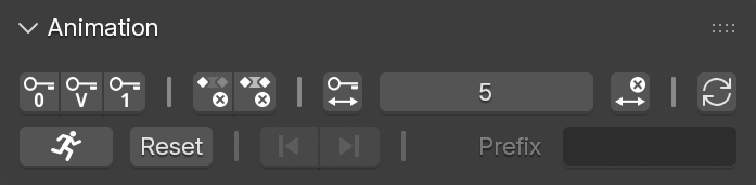
Overall, parts of the functionality in the Animation panel are designed to provide quick access to standard tools, since Blender does not provide direct access to shape key animation from a custom list. The Animation panel is divided into two rows of controls: one for basic keyframe animation and one for Shot Fix mode.
14.1 Keying
The Keying section of the Animation panel provides buttons for quickly creating or deleting keyframes for the selected target shapes in the list.
- Key Inactive: Sets a keyframe with a value of 0 for the selected shapes.
- Key Value: Sets a keyframe with the current value for the selected shapes.
- Key Active: Sets a keyframe with a value of 1 to activate the selected shapes.
- Delete Key: Removes the keyframe at the current frame for the selected shapes.
- Delete All Keys: Removes all keyframes for the selected shapes.
- Set Key Range: Sets three keyframes over a defined span of frames before and after the current frame. The number of frames before and after is defined by the Key Range value. The selected shape is set to inactive at the first and last frame and fully active at the current frame.
- Key Range: Defines the number of frames before and after the current frame used for blending the shape in and out. The value is also used by Shot Fix mode to blend in the first shape.
- Delete Key Range: Removes the set of three keyframes for the selected shape, as long as the current time is within that range.
14.2 Shot Fix
Shape keys are often used to correct deformation problems on the final animated mesh, caused by various factors. Rather than going back and addressing the issue by modifying the rig, it is often faster and more efficient to correct the affected area using a time-specific shape key.
At its core, Shot Fix is a workflow tool that allows a shape key to be applied at a specific frame and automatically blended with the previous and next shape keys.
Shot Fix can work in two different ways:
Pre-Deformation
If the mesh is deformed by an active rig through an Armature Modifier and the
Post Deformation
option is disabled,
Shot Fix
takes advantage of
SHAPES’ ability to create shape keys independent of the currently deformed mesh, which greatly helps when fixing deformation issues.
Post-Deformation
If the animated mesh has no deformation modifiers applied, such as an Alembic mesh, or if the
Post Deformation
option is enabled,
Shot Fix
creates a post-deformation shape key setup through Geometry Nodes. This allows working with object-space post-deformation shape keys for any kind of shape-based corrections.
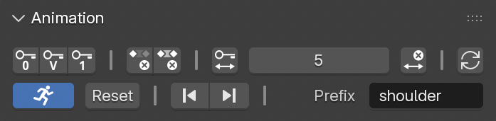
The Shot Fix section of the Animation panel provides the following controls:
- Shot Fix: Enables or disables Shot Fix mode. Creating a new shape while Shot Fix is active automatically sets keyframes for this shape and blends it with the previous and next shape keys.
- Reset: Resets all channels to zero, except for channels controlled by drivers. This is the same operator as the one in the Target List Menu.
- Previous Key/Next Key: Sets the current time to the frame of the previous or next shape key and selects the corresponding shape key in the Target List.
- Prefix: The prefix used to name and identify shape keys associated with Shot Fix. When Shot Fix is activated, the prefix is taken from the currently selected shape key item in the list.
When Shot Fix is active, selecting a shape key created in Shot Fix mode automatically moves the current time to the frame at which the shape was created.
14.2.1 Post-Deformation
When to Use
Post-deformation shape keys can be used when a shape needs to be created or adjusted on the already deformed mesh, and fixing the problem earlier in the rig is no longer practical or possible.
Post-deformation shape keys are ideal for shot fixes. They work best close to the pose they were created for. The further the pose moves away from that state, whether through bone rotation or other deformers, the less likely the post-deformation shape will produce acceptable results.
Whenever possible, pre-deformation shape keys remain the preferred and more stable solution.
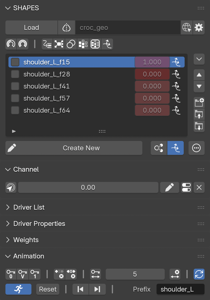
Pre vs. Post Deformation
For most workflows and applications, shape keys are applied pre-deformation to provide changes in shape based on the underlying undeformed, neutral mesh. These changes are then handed off to other deformers, such as binding the mesh to an armature to apply transformation changes with bones. The result is a stable and predictable way to apply shape changes, because they are always evaluated relative to the neutral mesh.
The downside to this approach is that the final appearance of a shape key is influenced by the following deformation steps. In some cases, a shape key can look correct on its own but appear noticeably different once the mesh is deformed. This is where SHAPES steps in, providing tools to edit shape keys in their final, deformed state, without having to compensate for how the shape looks on the neutral mesh.
In contrast, post-deformation shape keys are applied at the end of the deformation chain and therefore always depend on the current state of the deformed mesh. Even if the mesh is driven by an animated cache without any additional deformation, post-deformation shape keys allow further shape changes to be layered on top. This makes them particularly useful for creating animation-dependent effects or correcting deformation issues that would otherwise be impractical to resolve.
Applications
Post-deformation shape keys are often required when an animation has already been approved and may even be cached for later stages in production, but deformation errors become visible in rare or extreme poses. In these situations, the errors cannot be addressed by fixing and rebuilding the rig. Instead, they must be corrected per shot, directly on the animated and deforming mesh.
Object Space
Post-deformation corrections are applied at the very end of the deformation chain, on top of the already deformed mesh. The correction is stored as an offset vector per vertex and added back to the deformed surface at runtime, keeping the calculation lightweight and predictable. The trade-off is that the stored offset is tied to the orientation of the affected surface at the moment the correction was created.
Limitations
Because the correction is stored as an object-space offset relative to the pose in which it was created, it works best close to that pose. As the underlying deformation rotates the affected surface away from its original orientation, through bone rotation or other deformers, the fixed offset increasingly points in the wrong direction and the result degrades. For large rotations the correction can even pull geometry the wrong way.
In practice this is managed by keeping corrections within a limited range around their creation pose and blending their influence in and out, so the effect fades to zero before the deformation moves too far from the pose the shape was built for.
Before relying heavily on post-deformation shape keys, it is advised to perform a range of tests to ensure that the technical limitations do not cause issues in the intended production scenarios.
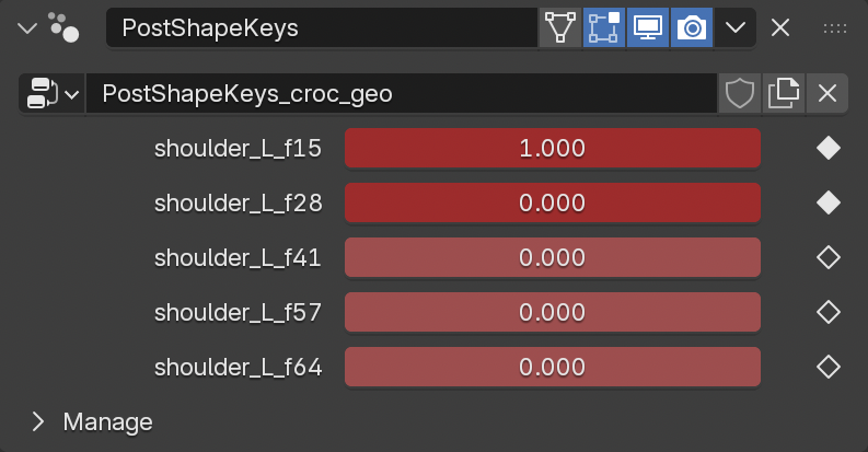
Technical Information
The post-deformation shape keys in
SHAPES
are implemented using Geometry Nodes to apply shape changes to the deforming mesh. Shape key delta vectors are stored in custom attributes and referenced by the node tree. When exiting
Edit Mode
after creating a corrective shape, the offset introduced by the edit is extracted and stored in object space.
At runtime the node tree simply adds the stored offset to the deformed position, so the values written during editing are applied directly without any further transformation. This keeps the calculation lightweight and predictable, at the cost of the correction being tied to the pose in which it was created.
14.2.2 Shot Fix Workflow
The following steps outline the general workflow for adding animated shape keys to fix deformation issues on an animated mesh:
- Go to the frame where the first correction is required.
- Activate Shot Fix.
- Enter a Prefix to identify the new shape and any following shapes.
- Press Create New to enter Edit Mode.
- Sculpt the shape to remove the unwanted deformation.
- Exit Edit Mode.
This creates a new animated shape key:
- The shape key is named using the provided Prefix and the current frame identifier.
- Two keyframes are created: one to blend the shape in a few frames before the current frame, based on the Key Range value, and one to activate the shape at the current frame.
- If Synchronize Animation is active, the keyframes are displayed in the Graph Editor or Dope Sheet.
For the first shape, it is often necessary to adjust the timing of the initial keyframe, where the shape is keyed with a value of 0.
Single Shapes
If only one corrective shape is required, set a manual keyframe at the frame where the shape should be deactivated.
Shot Fix
can then be turned off to finish.
Multiple Shapes
If additional corrective shapes are required, move to the next frame and repeat the steps above. Each new shape starts at the activation frame of the previous shape, and the previous shape receives a deactivation keyframe at the current frame.
Inserting a New First Shape
When adding a new corrective shape before the first one, it is treated as the initial shape, using the blend range defined by the
Key Range
value. After full activation, it is blended with the next shape, and the first keyframe of the next shape is adjusted accordingly.
Inserting Between Two Shapes
Adding a new corrective shape between two existing shapes automatically shifts the boundary keyframes of the neighboring shapes to create a proper blend with the new shape.
14.3 Synchronize Animation
When working with animated shape keys, it is often helpful to directly see the keyframes of the current shape selection, either as a visual reference or to refine the timing.
Due to Blender’s selection behavior, shape key animation is not always directly visible, especially when the object is not active.
When Synchronize Animation is enabled, the animation of the currently selected shape is displayed in the Graph Editor or Dope Sheet. The following steps are performed automatically:
- Disable the global scene option to show only selected keys.
- Select the FCurve of the current shape key.
- Disable Only Show Selected for the active editor.
- Set the editor’s Name Filter to the current shape key.
- Frame all keys of the selected FCurve.
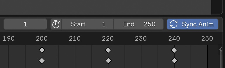
Because the state of Synchronize Animation can easily be overlooked when either the Animation panel is collapsed or the SHAPES panel is not visible, unexpected keyframe display behavior may not be immediately apparent.
To make the current state more visible, the Timeline, Graph Editor, and Dope Sheet each provide an additional Sync Anim button which reflects the current synchronization state.
API
Import/Export Setup
exportSetup(obj, filePath, exportCombos, exportList, exportDriver, exportRbf, exportShapeDriver, exportShapes, exportVertexGroups, exportWeightLinks, exportType)
Exports the shape key setup for the given object.
-
obj- The mesh object to export from. -
filePath- The full directory path where the data will be saved. The object name will be appended as a subfolder. -
exportCombos(bool) - Export combo data (default: True). -
exportList(bool) - Export target list data (default: True). -
exportDriver(bool) - Export non-SHAPES standard drivers (default: True). -
exportRbf(bool) - Export RBF Nodes node groups (default: True). -
exportShapeDriver(bool) - Export SHAPES-based drivers (default: True). -
exportShapes(bool) - Export shape key deltas (default: True). -
exportVertexGroups(bool) - Export vertex group data (default: True). -
exportWeightLinks(bool) - Export vertex group assignments (default: True). -
exportType- Defines the export mode. Enum: 'EXPORT_ONLY', 'DELETE_DRIVERS', 'DELETE_ALL', 'REBUILD_SETUP' (default: 'EXPORT_ONLY') -
separateVertexGroups(bool) - True to export vertex groups as separate files. False to combine all vertex groups into a single file (default: False).
Example:
SHAPES.core.export.exportSetup(myObject, "/shapes", exportType='EXPORT_ONLY')
importSetup(obj, filePath)
Imports a shape key setup from the specified file path.
-
obj- The mesh object the setup will be applied to. If no object is provided, the object name stored in the setup file will be used instead. -
filePath- The full path to the directory containing the exported setup files. The directory name must match the JSON file that contains the setup data.
Example:
SHAPES.core.export.importSetup(myObject, "/shapes/myObject")
Import/Export Shapes
exportShapeKeys(obj, shapeNames, filePath)
Exports the delta values of the specified shape keys on the given object to a JSON file.
-
obj- The mesh object to export from. -
shapeNames- A list of shape key names to include. -
filePath- The full directory path where the JSON file will be saved. The file will be named after the object.
Example:
SHAPES.core.export.exportShapeKeys(myObject, ["Smile", "Blink.L"], "/shapes")
importShapeKeys(obj, filePath)
Imports shape key delta data from a JSON file and applies it to the given object.
-
obj- The mesh object to which the shape keys will be added. -
filePath- The full path to the JSON file containing the exported shape key data.
Example:
SHAPES.core.export.importShapeKeys(myObject, "/shapes/myObject.json")
Import/Export Weights
exportWeights(obj, mapNames, filePath, separate)
Exports the vertex group data of the specified vertex groups on the given object to a JSON file.
-
obj- The mesh object to export from. -
mapNames- A list of vertex group names to include. Leave empty to export all shape key related vertex groups. -
filePath- The full directory path where the JSON file will be saved. The file will be named after the object or vertex group. -
separate(bool) - True to export vertex groups as separate files. False to combine all vertex groups into a single file (default: False).
Example:
SHAPES.core.export.exportWeights(myObject, ["Smile", "Blink.L"], "/weights", False)
importWeights(obj, filePath)
Imports vertex group data from a JSON file or a collection of JSON files and applies it to the given object.
-
obj- The mesh object to which the vertex groups will be added. -
filePath- The full directory path containing the vertex group JSON files.
Example:
SHAPES.core.export.importWeights(myObject, "/weights")
Duplicate
duplicateObject(obj=obj, original=True)
Creates a duplicate of the given object.
-
obj- The mesh object to be duplicated. -
original(bool) - IfTrue, duplicates the original (undeformed) mesh. IfFalse, duplicates the current (deformed) mesh.
Example:
SHAPES.core.actions.duplicateObject(obj=myObject, original=True)
Resources and Credits
Models used:
Croc
Model by Andrew Silke
create3dcharacters.com
Natalie
Model by Andrew Silke
create3dcharacters.com
Einar
Model by Blender Studio
studio.blender.org
Disclaimer
This documentation reflects the current state of SHAPES for Blender. Functionality and features may evolve in future releases.
Copyright (C) 2025-2026, Ingo Clemens, brave rabbit,
www.braverabbit.com
GNU GENERAL PUBLIC LICENSE Version 3